CAL & ADJUST
3-4
VersaPulse Select Service Manual
0621-499-01 03/94
®
®
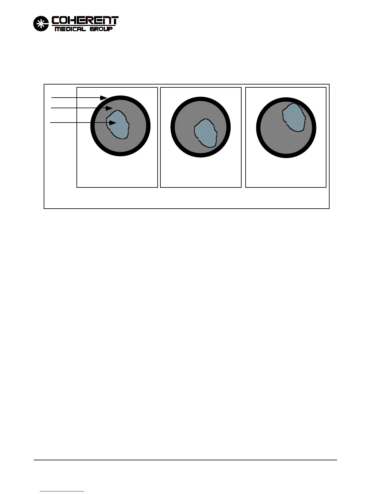
e.) Remove the fiber and examine it in the microscope. The burn and cladding will be easily
visualized if the other end of the test fiber is pointed towards a light source. The burn should be
approximately centered in the fiber optic and be well away from contact with the fiber cladding, as
shown in the drawing below. If the system fails this check, perform the YAG Channel Adjustments
(Topic 3.4.).
* If spot size is large, check individual YAG channels for proper alignment. Spot size should be less
than 210 µm in diameter and no closer than 70 µm from the cladding.
6. Confirm the calibration
Once the system passes steps 1 through 3, attach an Infratome fiber (nonsterile fibers for service
purposes are available through Technical Support) to the fiber port and direct its output into a
calibrated power meter. Go to user mode and fire the system to confirm that the measured power (as
seen on the power meter) is within ±10% of displayed average power across the range of pulse
energies and pulse rates.
7. Check consumable parts. Replace as necessary.
Check/replace the air filter. The air filter is mounted on the bottom of the system, held in place by a
removable bracket. A dirty filter should be cleaned or replaced.
Replace the DI filter after 6 months of use, or when the system has coolant conductivity faults.
Check/replace the coolant particulate filter. Replace the filter when it is visibly discolored.
8. Perform functional and safety checks.
a.) Attach a fiber.
ACCEPTABLE
NOT ACCEPTABLE
NOT ACCEPTABLE
Examining the test fiber end with the 100x microscope - The footprint will not always be circular,
but it should be approximately centered in the fiber and away from contact with the cladding.
Cladding
Core
Footprint
FIGURE 3.1 EXAMINING THE TEST FIBER BURN
12/95