THEORY OF OPERATION
4-20
Versapulse Select Service Manual
0621-499-01 01/94
®
®
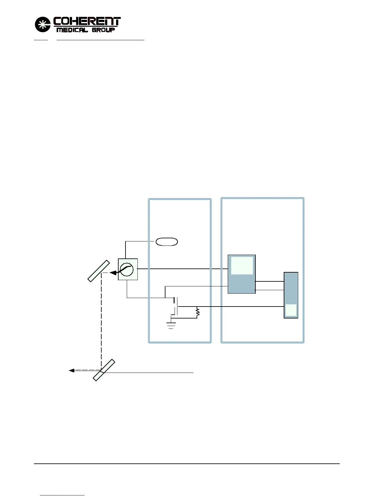
4.4.8 Aiming Diode Laser Circuit
The aiming diode laser module is mounted on the optics plate, just prior to the fiber focus assembly, and after
the safety shutter (the safety shutter can not block the diode aiming beam). The diode output is directed by a
folding mirror to a beam combiner. Both the folding mirror and beam combiner are adjustable, providing a
near and far adjustment to place the aiming beam coaxial to the treatment beam.
Refer to the Aiming Diode Laser Simplified Diagram (figure 4.6) and to the associated schematics in Section 8.
The aiming laser is supplied with 5 VDC through J15-5 on the Shutter PCB. The return line for the 5 VDC
supply is switched through Shutter PCB Q6. Q6 is turned on or off by the AIMON signal from the CPU PCB
(main processor digital I/O) to turn the aiming beam on or off.
Aiming beam intensity is controlled by variable resistance U49 on the CPU PCB connected to the aiming
beam module through the Shutter PCB (J15-2). The main processor sets the aiming beam intensity to high,
low, or medium by changing the variable resistance (U49) using the /AIMINC/ and /AIMU-D/ digital I/O
output lines.
5 VDC
P/O CPU PCB
P/O Shutter PCB
Variable
Resistance
U49
AIMON
/AIMINC/
/AIMU/D/
MµP
DIO
Laser Diode
Folding
(near)
Mirror
Beam Combiner
YAG BEAM PATH
Q6
FIGURE 4.6 AIMING DIODE LASER CIRCUIT SIMPLIFIED DIAGRAM