THEORY OF OPERATION
4-13
Versapulse Select Service Manual
0621-499-01 01/94
®
®
Assuming that the interlock loop is complete and the footswitch is depressed, the shutter will be opened
when the main processor asserts its digital I/O output SHTR DR to turn on Q2. Note that the SHTR DR
signal is gated on the CPU PCB by the safety processor /NOFIRE/ signal (AND gate U64-6). The safety
processor can prevent the shutter from opening by asserting /NOFIRE/ (low). The SHTR DR SNC line is a
main processor digital I/O input, allowing the processor to sense the presence or absence of the 24 VDC
through Q2 when the footswitch is not depressed.
Q1 operates momentarily each time Q2 turns on to bypass the shutter solenoid current around resistor R3 as
the shutter is moved into place, then turns off to drop the shutter solenoid current to a lower "holding" level.
Shutter position is monitored by LPT2 and LPT3 on the Dual Solenoid PCB. The two are complementary - for
the two shutter positions (opened or closed) one switch is blocked and the other is unblocked. Both devices
are supplied with 5 VDC and return ground from the Dual Solenoid PCB.
Sensed signals and drive signals are isolated through opto-isolators where the signals leave or enter the CPU
PCB.
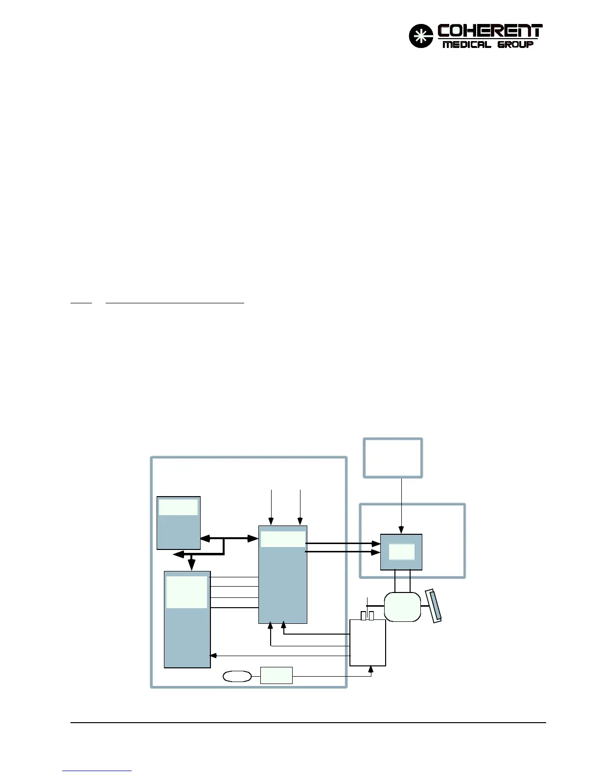
4.4.4 Servo Motor Control Circuit
A moving mirror is used to multiplex the (up to) four Ho:YAG head outputs into a single beam path. A servo
motor is used to precisely position this imaging mirror to any one of the four possible YAG head outputs.
The mirror is mounted to the end of the motor shaft, at a slight angle, so that as the shaft rotates through 360˚,
the mirror orientation changes. Between YAG pulses the mirror must be moved to and stopped at the point
in its rotation that aligns it with the output coupler of the head that will be fired next. After the pulse, it must
be moved to the next head to be fired, and so on for as long as firing continues.
POSITION
SENSE
MOTOR
SUPPLY
MOTOR
MOTOR
CONTROLLER
MAIN
PROCESSOR
DIGITAL
I/O
/SRVINDEX/
CHANNEL A
CHANNEL B
MAIN PROCESSOR
DATA BUS
MAIN
PROCESSOR
/SCOE/
/SCCS/
/SCALE/
R/W
/RSTD/ 2MHZ
DIRECTION
PULSE
5V ENCODE
24 VDC P/S
Servo Amp PCB
P/O CPU PCB
MIRROR
U60
24 VDC
FIGURE 4.3 SERVO MOTOR CONTROL CIRCUIT SIMPLIFIED DIAGRAM
12/95