THEORY OF OPERATION
4-12
Versapulse Select Service Manual
0621-499-01 01/94
®
®
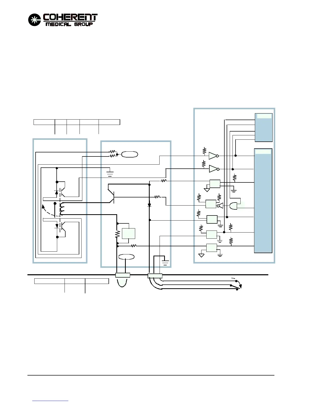
In addition to providing a sense input to the processors, the FOOT SW N.O. line completes the 24 VDC
ground return path for the shutter solenoid. If the footswitch is not depressed, there is no complete path for
current through the solenoid, so the shutter can not be removed from the beam path.
In a similar manner, the interlock loop is a part of the 24 VDC path to the shutter solenoid, connecting Shutter
PCB J12 pin 4 to pin 5 when the BRH loop is closed. If the loop opens, the 24 VDC path for the shutter
solenoid is opened and the shutter can not be removed from the beam path. The BRH SNC line is sensed as a
digital I/O input to the main processor, allowing the processor to detect an open BRH loop.
5 VDC
P/O CPU PCB
P/O Shutter PCB
P/O Dual Solenoid PCB
24 VDC
Q2
FTSW (shown depressed)
REMOTE
INTERLOCK
BRH SNC
FOOT SW N.C.
FOOT SW N.O.
SHTR DR SNC
SHTR SNC NO
SHTR SNC NC
Q1
LPT3
LPT2
/BRHOK/
/SHTRNC/
SHTRNO
/FTSWNC/
FTSWNO
SHTRDRSN
/NO FIRE/
SHTR DR
SµP DIO
MµP DIO
SHUTTER LPT3 LPT2 SHTRNO /SHTRNC/
closed on off high low
opened off on low high
MCT6
MCT6
MCT6
MCT6
MCT6
FOOTSWITCH FTSWNO /FTSWNC/
released high low
depressed low high
5
5
24
24
5
24
5
/FTSWNC/
FTSWNO
/SHTRNC/
SHTRNO
5
5
FIGURE 4.2 SHUTTER, FOOTSWITCH, REMOTE INTERLOCK SIMPLIFIED DIAGRAM
12/95