THEORY OF OPERATION
4-17
Versapulse Select Service Manual
0621-499-01 01/94
®
®
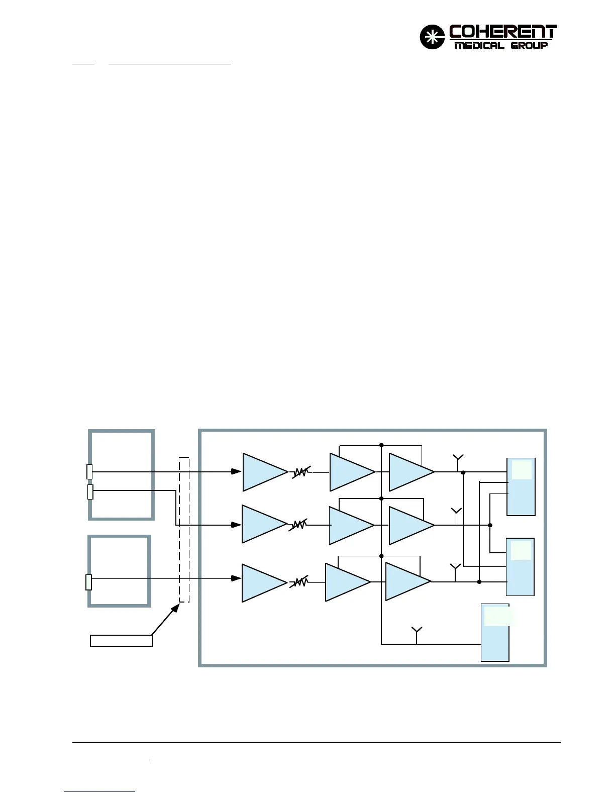
4.4.6 Energy Monitor Circuits
Refer to the Energy Monitor Circuits Simplified Diagram (Figure 4.5) and to the associated schematics in
Section 8. The VersaPulse Select measures the energy of each YAG pulse. Three separate channels measure
the energy. Two channels are required to provide safety redundancy; the third is provided to check the pulse
energy downstream from the low energy attenuator.
• ENERGY I - Monitors ENERGY I circuitry (redundancy).
• ENERGY II - Laser energy feedback loop signal.
• ENERGY III - Monitors energy delivered to fiber (after low energy attenuator).
The measurement is accomplished by directing a small percentage of the pulse to strike a pyrodetector. The
detector outputs a current the integral of which is proportional to the energy in the pulse. The current signal
is converted to a voltage, integrated, and then the result of the integration is held for reading by the processor
ADC circuits (both main and safety processors read the energy monitor circuit outputs after each pulse).
After the energy monitor outputs are read the circuits are reset and disabled until the next pulse. Each circuit
is calibrated by adjusting a potentiometer.
The remainder of this subtopic describes the ENERGY I circuitry and optics. The ENERGY II and ENERGY III
circuits operate in the same manner.
FIGURE 4.5 ENERGY MONITOR CIRCUITS SIMPLIFIED DIAGRAM
INTEGRATE
Transimpedence
Integration
Peak Holding
R7
R8
R9
ENERGY I
ENERGY II
ENERGY III
TP1
TP2
TP3
TP4
P/O Single
Sol. PCB
PYRO I
PYRO II
PYRO III
P/O Dual
Sol. PCB
MµP
ADC
SµP
ADC
MµP
TIMER
P/O CPU PCB
Shutter PCB
12/95