THEORY OF OPERATION
4-23
Versapulse Select Service Manual
0621-499-01 01/94
®
®
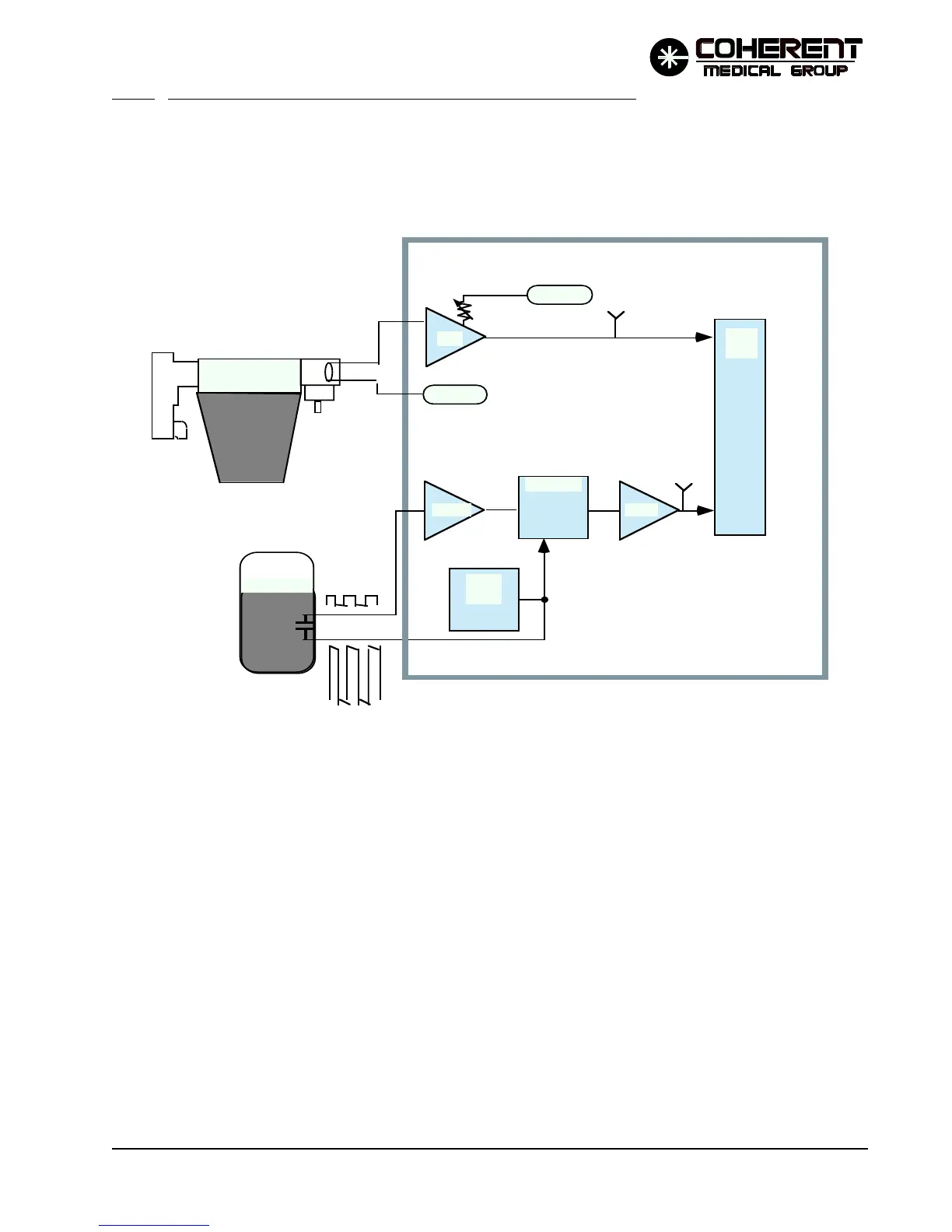
4.4.11 Coolant Temperature and Conductivity Monitoring Circuits
Coolant temperature and conductivity are monitored by sensors that report an analog voltage to the main
processor ADC circuit. Refer to the Coolant Temperature and Conductivity Monitor Simplified Diagram
below and to the associated schematics in Section 8.
TEMPERATURE - The temperature is monitored by a current source suspended in the coolant. Its current
output changes linearly with changes in coolant temperature. The current source is supplied with -15 VDC
from J4-5. The output of U17 (pin 1, also TP9) is:
.1 VDC/degree C (e.g., 3 Volts at TP9 indicates a sensed temperature of 30˚C)
R36 is an offset adjustment. U12-1 isolates the 10 VDC reference voltage from ADC U20.
CONDUCTIVITY - The coolant (distilled or de-ionized water) is maintained nonconductive to minimize
corrosion. A de-ionizing filter (DI filter) is included in the coolant loop to removed charged particles from the
coolant. The filter is a consumable item - it requires periodic replacement.
The main processor monitors the coolant conductivity to insure that it remains within an acceptable range,
and to confirm that the DI filter is operating properly.
FIGURE 4.9 COOLANT TEMP & CONDUCTIVITY MONITORING SIMPLIFIED DIAGRAM
COOLANT RES.
U17
-15 VDC
10 V Ref
TP9
MµP
ADC
DEMOD
70 Hz
OSC
P/O CPU PCB
TP10
U17-14 U17-8
Temp in C = 10(Voltage @ TP9)
Conductivity in µSeimans = .25(Voltage @ TP10)
WATER
FILTER
R36
(coolant temp)
(conductivity)
12/95