THEORY OF OPERATION
4-22
Versapulse Select Service Manual
0621-499-01 01/94
®
®
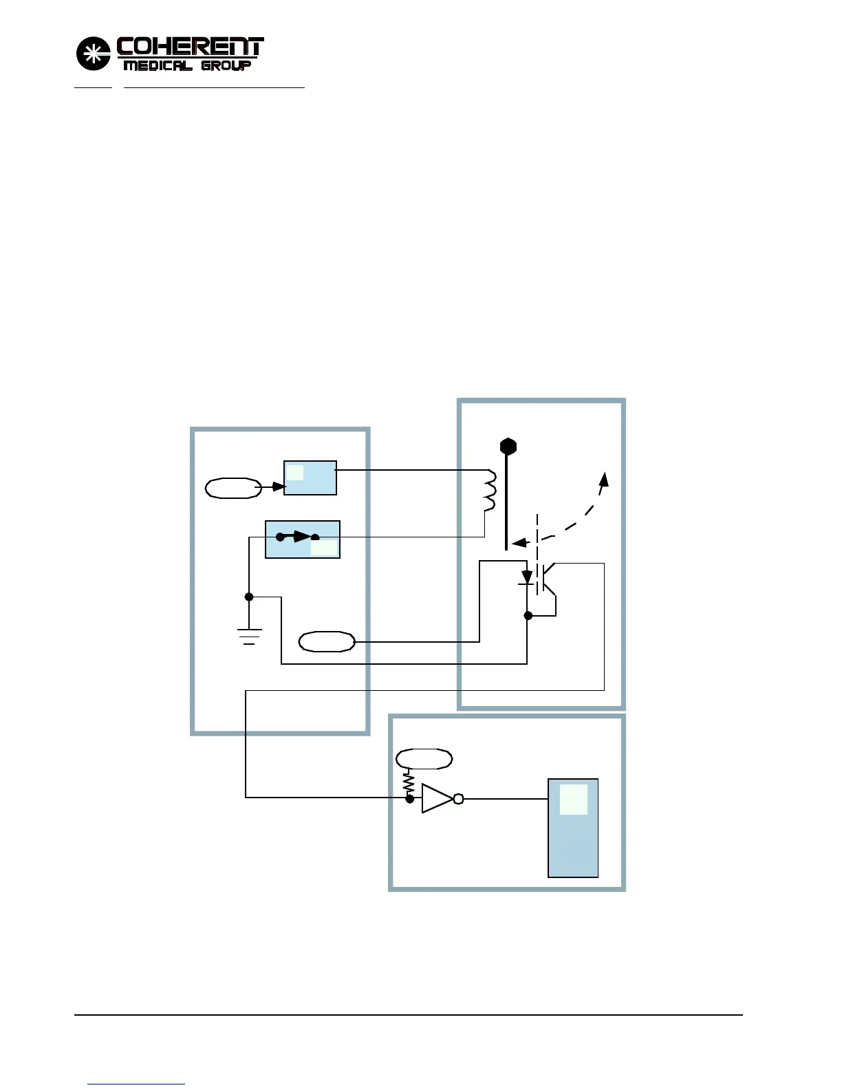
4.4.10 Service Attenuator Circuit
The service attenuator is inserted into the beam path during servicing to prevent damage to the end of an
attached fiber (and blast shield). It is used when the alignment of the YAG beam is not known to be good into
the end of the fiber. The attenuator provides greater than 99% attenuation. A service switch located on the
Shutter PCB is activated by the servicing engineer in order to operate the service attenuator. The switch turns
the service solenoid on, placing the attenuator in the beam path. Position is sensed by a slotted optical switch.
Refer to the Service Attenuator Simplified Diagram below and to the associated schematics in Section 8.
Closing switch SW1 on the Shutter PCB provides the ground return path for the 24 VDC supply to the
solenoid. The solenoid energizes to move the attenuator into the beam path. The attenuator position is
monitored by slotted optical switch LPT1. The SER SNC N.O. line is opened when the switch is blocked and
grounded when the switch is not blocked. The signal is sent through the Shutter PCB to the main processor
digital I/O on the Controller PCB (signal SER ATN NO).
P/O CPU PCB
MµP
DIO
P/O Shutter PCB
P/O Dual Solenoid PCB
24 VDC
5 VDC
SW1
Q5
In the beam path
when energized.
SER SNC N.O.
SER ATEN NO
5 VDC
/SERATNO/
FIGURE 4.8 SERVICE ATTENUATOR SIMPLIFIED DIAGRAM
12/95