THEORY OF OPERATION
4-19
Versapulse Select Service Manual
0621-499-01 01/94
®
®
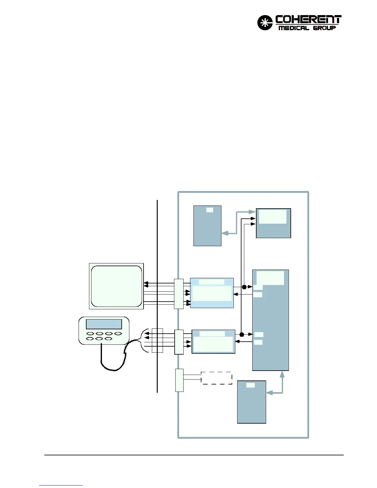
Both the main and safety processors decode the user input information to determine if the horizontal and
vertical information indicates that the user has pressed an area of the screen that represents a valid user
input. In user mode, the main processor does not respond directly to user inputs: instead, the main processor
responds to messages from the safety processor through the shared memory indicating an input has oc-
curred. In service mode the main processor responds directly to control panel inputs.
The remote control communicates with the main and safety processor in the same way, over the B channels of
the main and safety processor UARTs.
The RS232 port is provided for use in automated testing, and is not used in normal operation.
A beeper (not shown on simplified schematic) is attached to the main processor programmable timer through
audio amplifier U38. The beeper is mounted inside the touch screen display. The main processor writes to the
timer to drive the beeper. The beeper is used in this manner to draw the user's attention to various conditions
(e.g., input accepted, input rejected, fault, etc). Beeper volume is adjusted by R98.
DIFFERENTIAL BUS
DRIVER (p/o U95) &
RECEIVER (p/o U96)
DIFFERENTIAL BUS
DRIVER (p/o U95) &
RECEIVER (p/o U96)
CHANNEL A
CHANNEL B
RXA
TXA
RXB
TXB
RS232 BUS, not used
during normal operations.
To Programmable
Timer U45
J9
J6
P/O CPU PCB
MµP
DUAL UART
CONTROLLER
SµP
DUAL UART
CONTROLLER
SµP
MµP
TOUCH SCREEN
WIRED REMOTE
FIGURE 4.6 TOUCH SCREEN AND REMOTE CONTROL SIMPLIFIED DIAGRAM