THEORY OF OPERATION
4-26
Versapulse Select Service Manual
0621-499-01 01/94
®
®
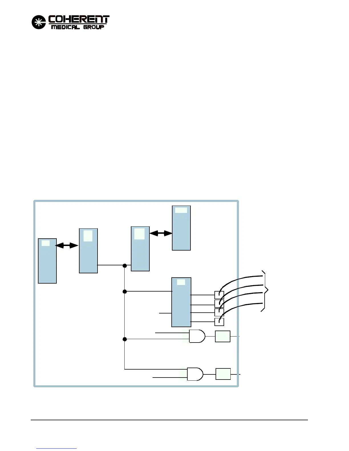
Reporting the "nofire" condition to the main processor through the main processor digital I/
O at U44 pin 20.
U78 "B" channel operates the three SMUX lines that select the input to the safety processor ADC
circuit at multiplexer U78.
U78 channel "C" provides timing functions for the safety processor, including the 1 msec interrupt.
The safety processor writes to its digital I/O to set the SMUX0, SMUX1, and SMUX2 lines. These three lines
are the select inputs to multiplexer U76. Based on its select inputs, the multiplexer will select one of the four
analog voltages on its input lines for output to analog to digital convertor U68. U68 converts the DC voltage
input to a digital value and stores it in registers U69 and U70. The safety processor can then read in the digital
value representing the analog voltage.
The ADC circuit can read the analog outputs from the energy monitor circuits and the HVDAC voltage.
U93, DIS I and DIS II are used to provide a 2 digit seven segment display for the safety processor. The display
is used in system testing/de-bugging.
MµP
DIO
SµP
SµP
DIO
HVENTM
SHTRDR
FIREPLS
U42
TRIG 1
TRIG 2
TRIG 3
TRIG 4
MµP
/NOFIRE/
MCT6
MCT6
RS ENABLE
SHTR. DR
P/O CPU PCB
U64-3
U64-6
TO ISOLATED
TRIGGER PCB
When the /NOFIRE signal is aserted low:
1. Opens the four trigger
outputs from U42.
2. Forces U64-3 low, disabling
the HVPS from charging the main
charging capacitor.
3. Forces the U64-6 low, disabling
drive to the shutter solenoid.
4.) DIO input to main processor.
FIGURE 4.10 SAFETY PROCESSOR NOFIRE CIRCUIT SIMPLIFIED DIAGRAM
12/95