1-9
VX-4000 VHF Low-band Service Manual
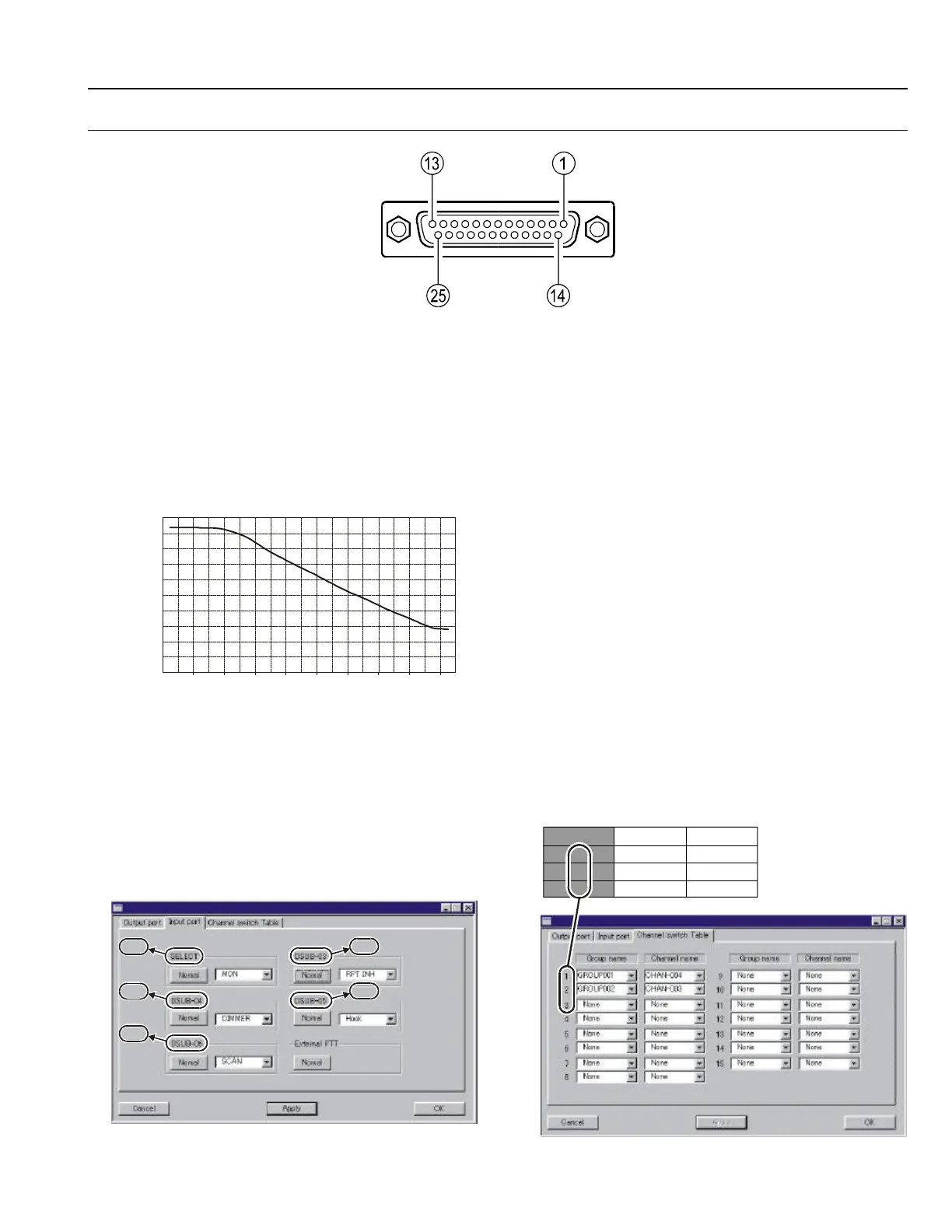
DSUB 25-PIN ACCESSORY CONNECTOR
Pin 1: RSSI [Analog Output]
A DC voltage proportional to the strength of the
signal currently being received (Receiver Signal
Strength Indicator) is provided on this pin. This
low impedance output is generated by the re-
ceiver IF sub-system and buffered by an internal
op-amp. Typical voltages are graphed as follows:
0
1259 398 125 398 12.5 4 1.25 0.4
0.04
SSG Input Level (uV)
DSUB 25-Pin Numbering
Pin 2, 3, 4, 5 & 6: AI1, AI2, AI3, AI4 & AI5
[Universal Input Port]
These input port features can be programmed via
the CE35 programmer. The same item can not be
chosen twice.
To select the “Input port” page, (View à Com-
mon View à DSUB-25pin connector à Input
port).
LOGIC level (+5V / 0V) input (Low active).
High Impedance input.
None
MON This feature is the same as pressing
and holding in the Monitor key.
DIM LCD illumination dimmer “on.”
Hook Activates the Hook1 feature.
SCAN Activates the scanner.
G-SCAN Activates the Group scanner.
RPT INH Disables the repeater feature during
Multi Deck operation.
ENG Activates the Emergency feature.
Home Switches to the Home Channel.
CH SW0 Memory channel recall
(Channel Switch Table bit 0)
CH SW1 Memory channel recall
(Channel Switch Table bit 1)
CH SW2 Memory channel recall
(Channel Switch Table bit 2)
CH SW3 Memory channel recall
(Channel Switch Table bit 3)
Example
If you assign “CH SW0” and “CH SW1” to the
Universal Input Port, you can recall Channels 1~3
as shown below.
Channel CH SW0 CH SW1
1 1 0
2 0 1
3 1 1
Pin 2
Pin 4
Pin 6
Pin 3
Pin 5
 Loading...