Electrical Installation
Vertiv | Liebert CRD10 | User Manual 60
Master unit will share teamwork parameters, temperature and humidity set point, proportional band, dead
band, fan control mode, compressor control mode to the slave unit. Slave unit upload run status, alarm signs to
the master unit.
Unit with address 0 is defined as the master unit. Units with the non-zero address are defined as the slave units.
Teamwork parameters only can be set in master unit and share to the slave units. Slave units can only set their
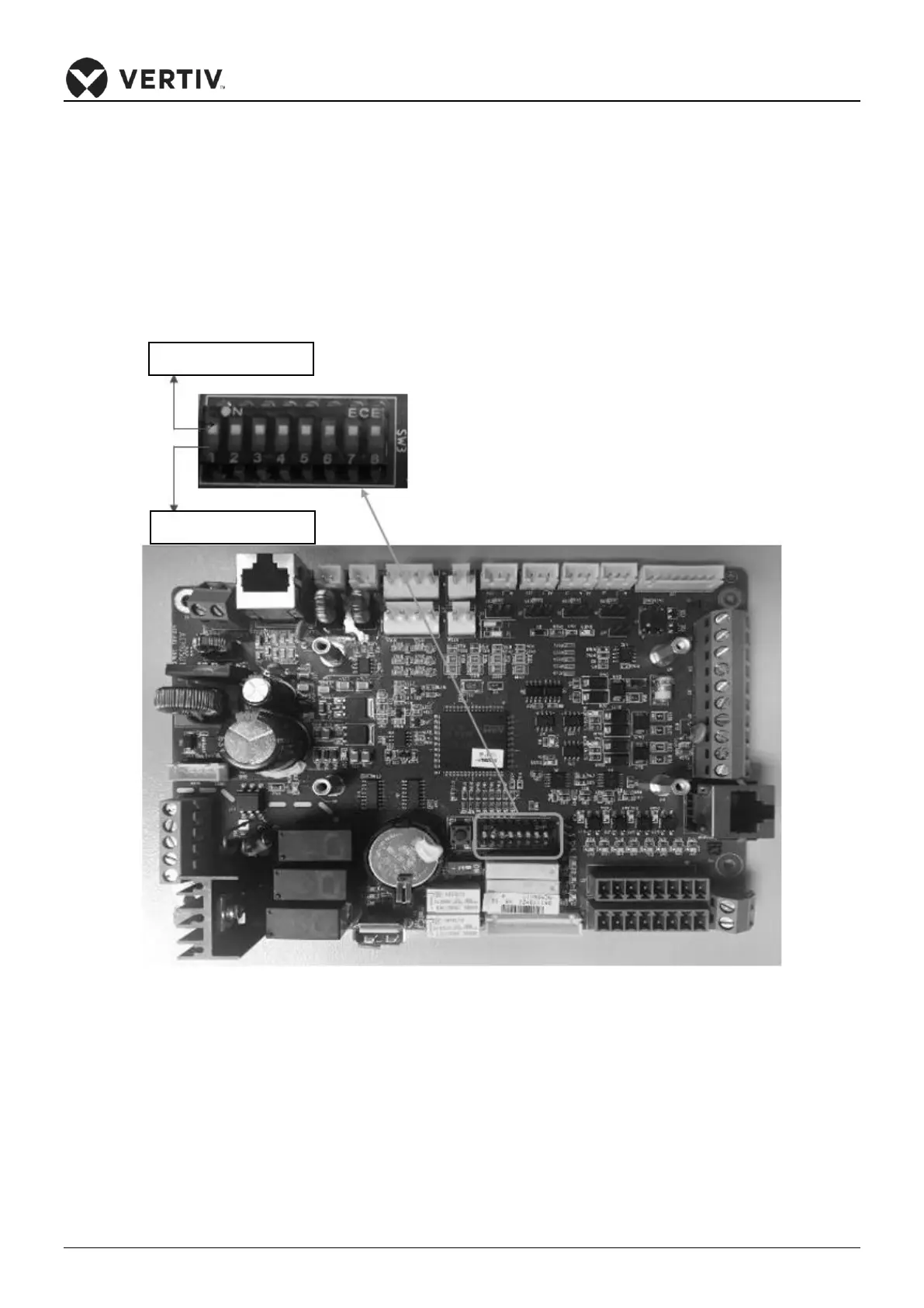
own unit address. After the teamwork connection is completed, set the unit CAN ID through the DIP SW3 of the
PACC board. The address setting method is shown in the Figure 4-8 and Table 4-4.
Figure 4-8 Significance of the DIP SW3 position