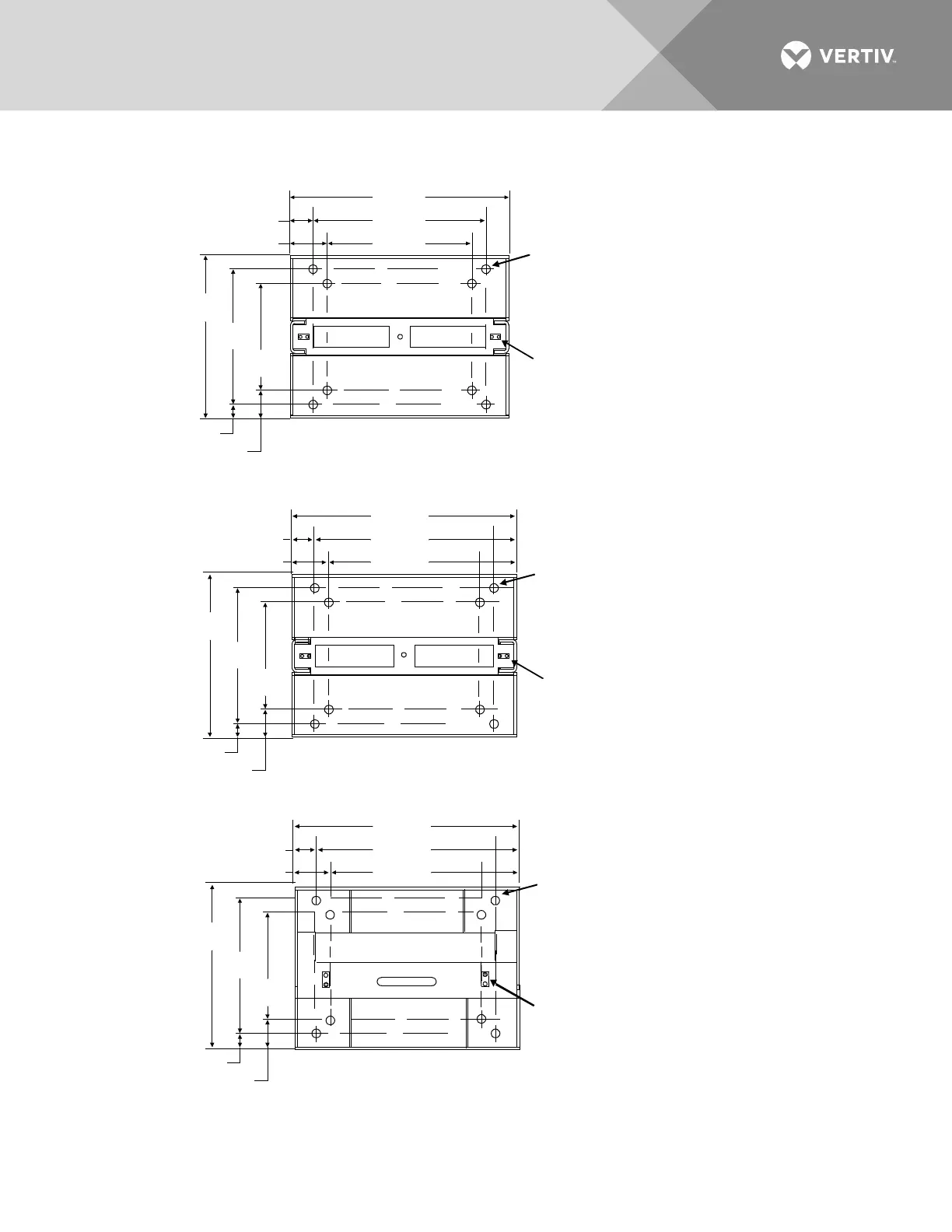
EasyManuals Logo

Vertiv NetSure 2100 Series Installation Manual

Vertiv NetSure 2100 Series
86 pages
To Next Page IconTo Next Page
To Previous Page IconTo Previous Page
Page #17 background imageLoading...
Page #17 background image
Vertiv | NetSure™ 2100 Series -48 VDC Power System Installation Manual (IM582138000) | Rev. C
17
Figure 2:
Relay Rack Floor Mounting Dimensions - 19
Part No. 559823
Part No. 559824
13.50
16.13
20.38
2.13
3.44
9.88
12.53
15.00
1.24
2.56
0.875 Dia.
(8 Places)
Masked for Frame Ground Lug
0.281 Dia. Holes on 0.625 Centers
(Top of Rack, 2 Places)
Masked for Frame Ground Lug
0.281 Dia. Holes on 0.625 Centers
(Top of Rack, 2 Places)
14.13
16.75
21.00
2.13
3.44
9.38
12.03
15.00
1.49
2.81
0.875 Dia.
(8 Places)
Notes:
1. All dimensions are in inches.
Masked for Frame Ground Lug
0.334 Dia. Holes on 0.625 Centers
(Top of Rack, 2 Places)
Part No. 563922
15.69
18.31
21.80
1.76
3.07
12.34
15.00
18.00
1.50
2.83
0.812 Dia.
(8 Places)

Table of Contents

Other manuals for Vertiv NetSure 2100 Series

Questions and Answers:

Question and Answer IconNeed help?

Do you have a question about the Vertiv NetSure 2100 Series and is the answer not in the manual?

Vertiv NetSure 2100 Series Specifications

General IconGeneral
BrandVertiv
ModelNetSure 2100 Series
CategoryPower Supply
LanguageEnglish

Related product manuals