Vertiv | NetSure™ 2100 Series -48 VDC Power System Installation Manual (IM582138000) | Rev. C
External Alarm, Reference, Monitoring, and Control Connections
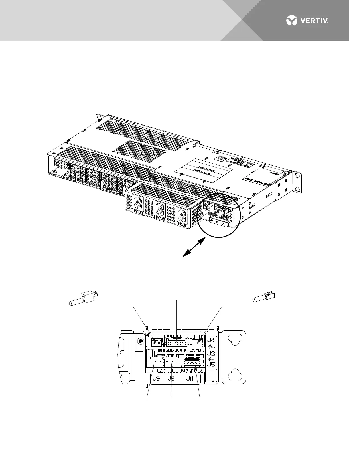
Connection Point Locations
Refer to Figure 28.
Figure 28:
External Alarm, Reference, Monitoring, and Control Connection Point Locations (cont’d on next
page)
J9
Temp
Probe 1
J5
Customer RS-485
Connection or
564702 Termination
Resistor Assembly
RS-485
1A
RS-485
1B
CAN
LOW
CAN
HIGH
J4
Customer CAN
Connection or
564703 Termination
Resistor Assembly
J3
Customer Digital
Inputs and Outputs
Via Cable P/N
565286
(See Detail A)
J8
Temp
Probe 2
J11
Optional
External
IB4
Termination Resistor
Assembly, P/N 564702
Termination Resistor
Assembly, P/N 564703

 Loading...


