Vertiv | NetSure™ 2100 Series -48 VDC Power System Installation Manual (IM582138000) | Rev. C
Optional Battery Disconnect Circuit Breaker Installation
Procedure
1. To install an optional battery disconnect circuit breaker onto the battery tray, perform the procedure
detailed in Figure 14.
2. Battery tray wiring is shown in “Installing and Connecting Batteries in an Optional List 93 or 94 Battery
Tray (if furnished)” on page 70.
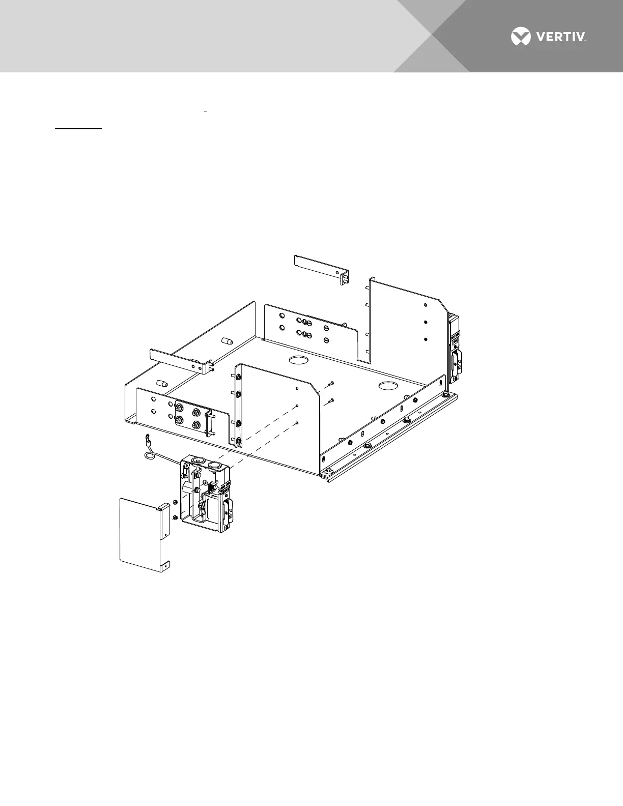
Figure 14:
Installing Optional Battery Disconnect Circuit Breaker onto a List 93, 94 Battery Tray
Battery Disconnect
Circuit Breaker Assembly
(left side kit shown,
right side kit available)
1. Remove the cover from the battery
disconnect circuit breaker assembly.
2. Secure the battery disconnect circuit
breaker assembly to the battery tray
using 6-32 x 1/2” screws and 6-32
KEPS nuts (2-places).
3. Secure the ground lead under a battery
tray relay rack mounting bolt.
4. After wiring to the battery disconnect
circuit breaker, replace the cover.

 Loading...


