Vertiv | NetSure™ 2100 Series -48 VDC Power System Installation Manual (IM582138000) | Rev. C
Checking System Status
Procedure
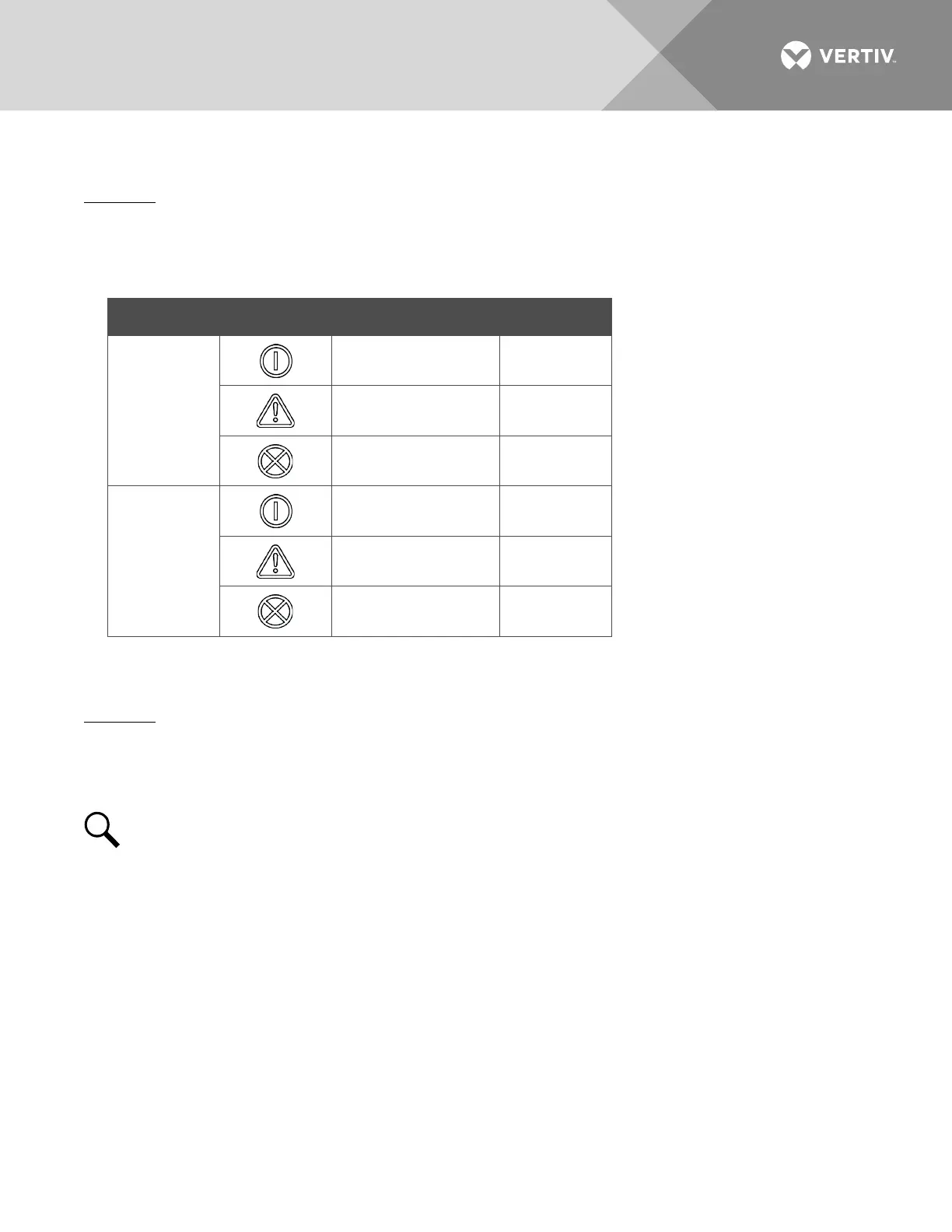
1. Observe the status of the indicators located on the controller and rectifiers. If the system is operating
normally, the status of these is as shown in Table 5.
Table 5:
Status and Alarm Indicators
Component Indicator Normal State
Mini Control
Unit
Status (Green) On
Minor Alarm (Yellow) Off
Critical or Major
Alarm (Red)
Off
Rectifier
Modules
Power (Green) On
Protection (Yellow) Off
Alarm (Red) Off
Final Steps
Procedure
1. If any controller configuration settings were changed, refer to the Mini Control Unit Instructions
(UM1M831ANA) and save a copy of the configuration file. This file can be used to restore the controller
settings, if required, at a later date.
NOTE!
Provided on a USB drive furnished with the system is a controller configuration drawing
(C-drawing) and the controller configuration files loaded into the controller as shipped.
2. Verify all rectifier modules and the controller are fully seated, latched, and the latch handle screws
secured.
3. Verify there are no external alarms and the local indicators are as shown in Table 5.

 Loading...


