Vertiv | NetSure™ 2100 Series -48 VDC Power System Installation Manual (IM582138000) | Rev. C
Installing an Optional External IB4 Kit P/N 559239
Procedure
NOTE!
Refer to
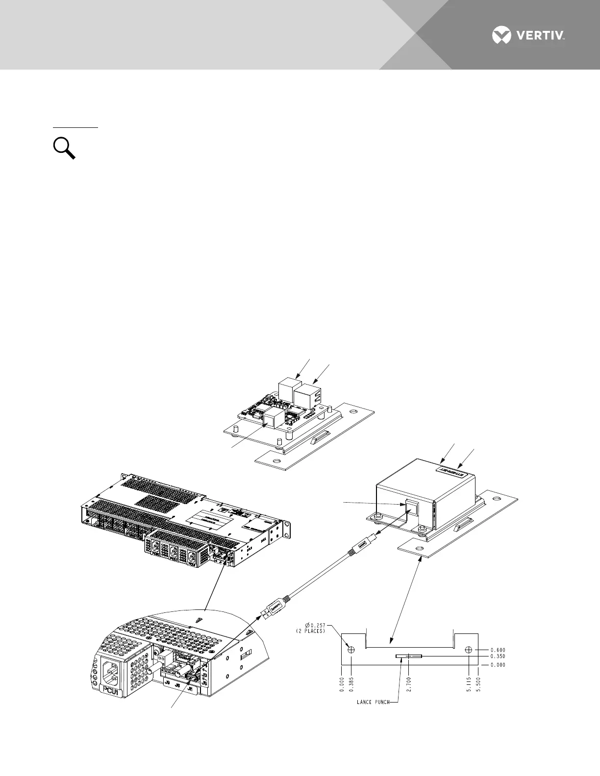
Figure 23
as this procedure is performed.
1. Mount the external IB4 assembly within 3 feet of the system interface connector (J11).
2. Plug the cable ordered with the external IB4 assembly between the assembly and the system interface
connector (J11) as shown in Figure 23.
3. If the system is in operation, reboot the Mini Control Unit.
Local Menu Navigation:
At the Main Screen, press ENT and ESC at the same time to reboot the Mini Control Unit.
Web Menu Navigation:
Advance Settings Menu / SW Maintenance Tab / Reboot Controller button.
Figure 23:
Installing an Optional External IB4 Kit P/N 559239
10M Ethernet
Port (RJ-45)
LAN Connection
USB-B Port
(Customer connected
to power shelf.)
USB-A Port
(not used)
Rear
External IB4
Interface Connector
Location (J11)
Mounting
Bracket
External IB4 Controller
Interface Board Kit, P/N
559239
Cable P/N 147605
(3 feet) (ordered
separately)
10M Ethernet
Port (RJ-45)
LAN Connection
USB-B Port
(Customer connected
to power shelf.)
USB-A Port
(not used)
Top Cover
Removed

 Loading...


