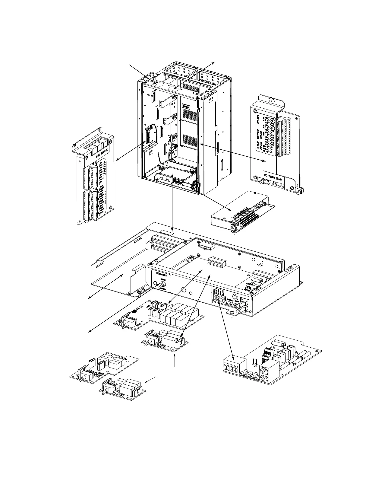
EasyManuals Logo

Vertiv NetSure 7100 Series User Manual

Vertiv NetSure
7100 Series
106 pages
To Next Page IconTo Next Page
To Previous Page IconTo Previous Page
Page #16 background imageLoading...
Page #16 background image
Vertiv™ NetSure™ 7100 Series -48 VDC Power System User Manual
6
Figure 3.1 Circuit Card Locations (Main Bay)
Optional SM-DU+ and
Shunt Interface Board
4-Row Cabinet Shown,
Others Similar
(Front Door Removed in
Illustration for Clarity)
Controller
System Interface
Circuit Card
OR
Optional LVD
Driver Circuit Card
Optional LVD
Inhibit Switch
(factory installed
if option specified)
Optional LVD Driver
Lite Circuit Card
Optional Manual Battery
Disconnect Circuit Card
(Main Bay Only)
IB2 (Main Bay Only)
(Interface Board)
(located on inside side panel)
Optional EIB (Main Bay Only)
(Extended Interface Board)
(located on inside side panel)
Optional IB4 (Main Bay Only)
(Second Ethernet Port Board)
Optional Second IB2 or EIB (Main Bay Only)
(underside of cover)

Table of Contents

Other manuals for Vertiv NetSure 7100 Series

Questions and Answers:

Question and Answer IconNeed help?

Do you have a question about the Vertiv NetSure 7100 Series and is the answer not in the manual?

Vertiv NetSure 7100 Series Specifications

General IconGeneral
BrandVertiv
ModelNetSure 7100 Series
CategoryPower Supply
LanguageEnglish

Related product manuals