Vertiv™ NetSure™ 7100 Series -48 VDC Power System User Manual
SM-DU Circuit Card
The SM-DU is used in supplemental bays in place of a controller. The SM-DU monitors the bay and reports to the controller. The
controller sends commands to the SM-DU to fulfill battery management and load control functions according to the received data.
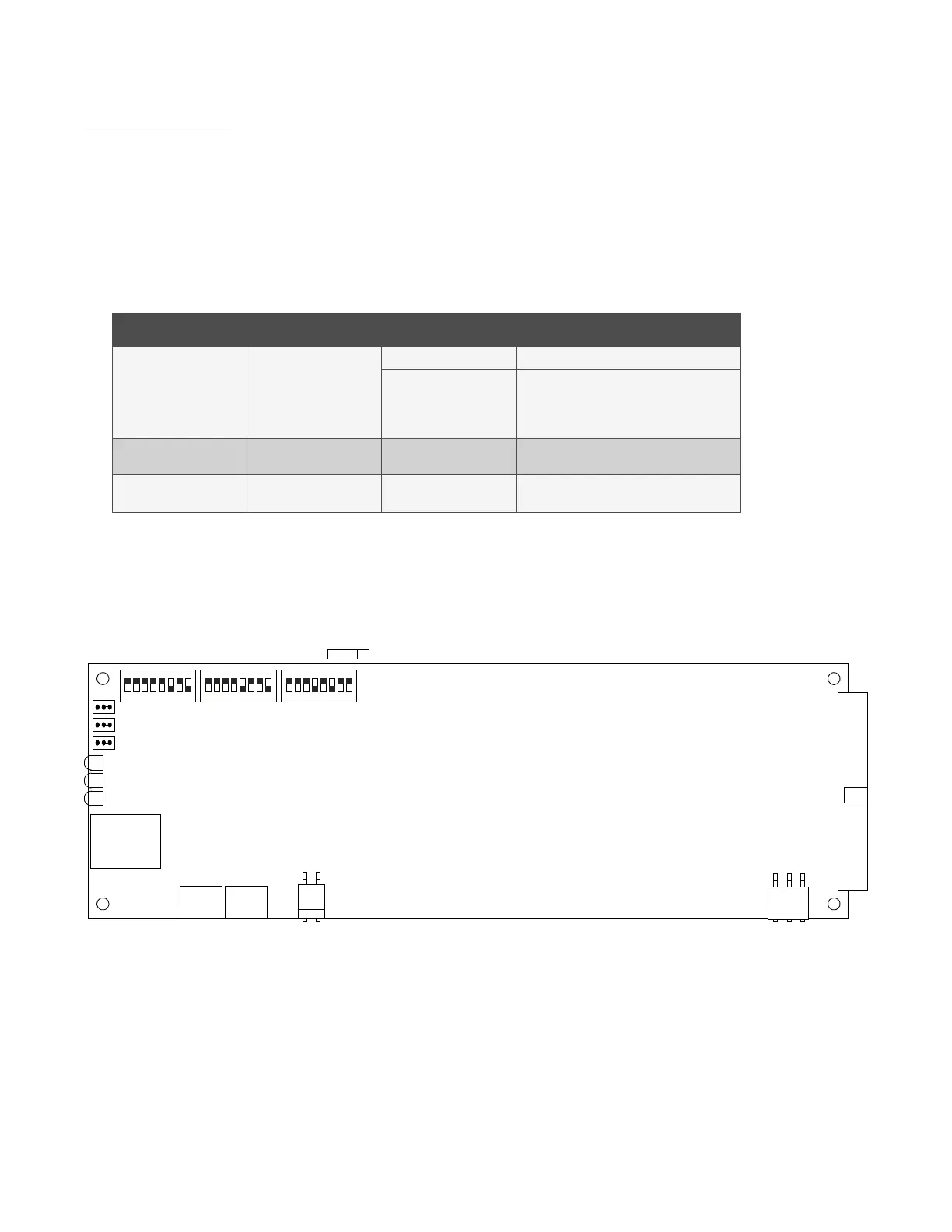
There are three (3) status and alarm indicators located on the SM-DU. The functions of these indicators (from top to bottom as
shown in the illustration) are as shown in Table 3.1. Refer to Figure 3.6 for location.
Table 3.1 SM-DU Indicators
Indicator Normal State Fault State Fault Cause
Operation
(Green)
On
Off SM-DU is non-operational.
Flashing
A 1/3Hz flashing indicates the SM-DU is
being identified by the Controller.
A 1Hz flashing indicates a communication
failure.
Alarm
(Yellow)
Off On A minor alarm.
Alarm
(Red)
Off On A critical or major alarm.
Figure 3.6 SM-DU Circuit Card
Supplemental
Bay Addressing
8 7 6 5 4 3 2 1 8 7 6 5 4 3 2 1 8 7 6 5 4 3 2 1
SM-DU Circuit Card
S 1S2S 3
JP1
JP2
JP3
J5
J4J4A
J3
J1
J2
Power
CANRS485
R
S
48
5
RS232
ON
OFF
Green Indicator (Operation)
Yellow Indicator (Alarm)
Red Indicator (Alarm)

 Loading...


