Sr. No. Item Description
1 Cableway Compartment Designated for customer connections.
2 MCCB Compartment Housing unit for MCCB.
3 MCCB – UL489 fixed mount circuit breaker Equipment designed to break electrical circuit if tripped.
4 ACB – UL1066 draw out circuit breaker Equipment designed to provide protection for overcurrent and short circuits using air.
5 Neutral Busbar
Voltage difference to each phase is approximately equal in magnitude and are equally
spaced in phase.
6 Main Busbar Carries the majority of the current.
7 Panel Flange Connection Connection point between switchboard and busway route in a facility.
8 Ground Busbar Ground network for the lineup with taps.
9 Instrument Compartment Designated as the metering and control section.
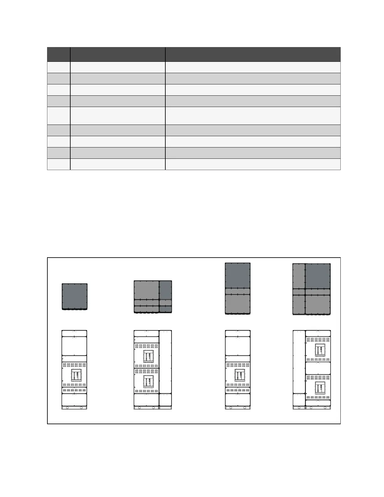
2.4 Typical Switchboard Layouts
Switchboards provide typical layouts for ACBs and MCCBs within the lineup. Typical layouts include front and rear access,
with single and double stack ACBs in individual sections. See Figure 2.6 below .
Standard MCCB columns with MCCBs stacked on top of each other in individual sections. See Figure 2.7 on the facing page .
MCCB’s use rotary handles for turning the breakers on and off. In a front access only switchboard, there is a cableway for field
termination.
Figure 2.6 Typical ACB Layout
Front Access - Single ACB Front Access -Double ACB Rear Access - Single ACB Rear Access - Double ACB
4 Proprietary and Confidential ©2024 Vertiv Group Corp. 2 Introduction
Vertiv™ UL891 Switchboard Installer/User Guide