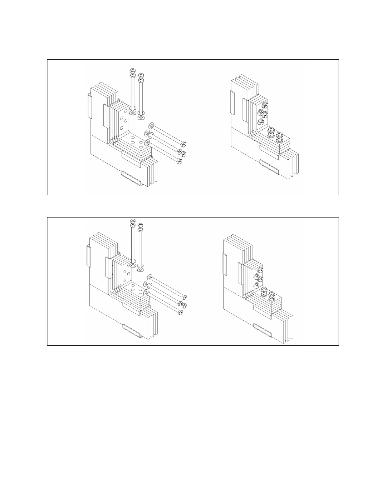
Figure 4.29 Transition Bus Connection – Traditional Fish Plates 3000A (3X80X10)
Figure 4.30 Transition Bus Connection – Traditional Fish Plates 4000A (3X100X10)
4.6.2 Ground Bus Connection
The Figure 4.31 on the next page provides a typical representation of the arrangement of adjoining ground bus at panel
splits. Refer to Typical Ground Layout on page8 and/or project specific drawings for ground bus location details based on
the configuration of the switchboard (top vs bottom incoming/outgoing, front vs rear access and so on). When joining the
ground bus, apply torque settings for M10 hardware as set forth in Table 7.1 on page43 .
4 Installation Proprietary and Confidential ©2024 Vertiv Group Corp. 35
Vertiv™ UL891 Switchboard Installer/User Guide