4.3 Considerations for Installation
Use methods described in Unloading off Pallet on page14 to move the switchboard into its final position. Use extreme caution
and appropriate practices and equipment when doing so. Note that most switchboards will be heavy from top and front.
Switchboards are shipped as a whole or in individual sections that are joined together. Determine the orientation of the
switchboard or of each split by the manufacturer drawings and markings on the units. A drawing will provide the splits in order
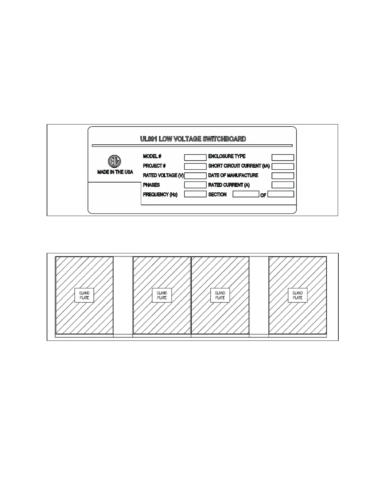
and where they will join. Each section will have a label that states ‘SECTION # OF #’ (see Figure 4.3 below ). These labels are
in either a control or breaker section closest to eye level of an average human.
Figure 4.3 Label Illustration
Most switchboard sections are designed to be front aligned, manufacturer drawings provided will show footprint details. The
orientation on the drawings must be maintained as specified (see Figure 4.4 below ).
Figure 4.4 FrontAligned Switchboard
Sections of the switchboard may contain factory bus and/or cabling to connect power between splits and other components.
Installers should note location and orientation of all splice plates and/or cables to be installed once sections are joined and in
place. All splice plates and hardware will be provided to complete these connections. These items will be contained in a box,
either in one of the splits or on a pallet by themselves. Keep all bus and hardware in a clean and protected environment to
guard against damage until they are installed. Make sure to keep factory installed component cables protected from potential
damage when moving sections into place.
Outdoor switchboard sections will ship with uninstalled roof caps for each split along the panel. Make sure these roof caps and
associated hardware are kept in a clean and protected environment to protect against potential damage. Once the split is/are
in their permanent location, then install the roof cap. Where two or more type 1A or type 3R switchboard sections come
together, they should first be aligned, then all sections leveled. Once aligned and leveled, join the switchboard sections
together.
4 Installation Proprietary and Confidential ©2024 Vertiv Group Corp. 23
Vertiv™ UL891 Switchboard Installer/User Guide