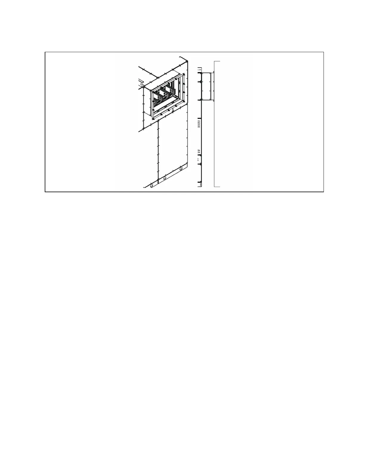
Figure 4.8 Typical XFMR Connection
4.6 Electrical Connections
Several methods may be used to make electrical connections within switchboard splits. One or all methods may be used in a
section and/or a switchboard lineup. These include bus splice plates, field terminal cabling, and busway connections. Examine
the manufacturer’s drawings for details pertaining to each switchboard section. Remove covers and side sheets as needed to
access switchboard connection points. Retain all covers and mounting hardware for reassembly. Protect hardware and parts
from moisture, debris, and other potential causes for damage.
4.6.1 Fish Plates
Fish plates are pieces of bus bar that adjoin the main horizontal and/or vertical bus that runs between different sections of the
switchboard. Depending on the configuration and alignment of the switchboard, multiple fish plate configurations can be
used. The different types of splice plates and connections are identified below based on amperage. Various amperages can be
configured with either two or three bus laminations per phase, identified in parenthesis along with each amperage below.
Apply torque settings for M10 hardware as set forth in Table 7.1 on page43 .
4 Installation Proprietary and Confidential ©2024 Vertiv Group Corp. 27
Vertiv™ UL891 Switchboard Installer/User Guide