Item Description
5 5 Wraps (2X)
6 Cable lugs (3X)
7 Roof or floor entrance
4.6.4 Busway
A switchboard may have one or more busway flange connections. The switchboard can accept various manufacturer’s
busway flanges. The busway can feed the switchboard, be fed by the switchboard, or both. The switchboard uses internal
risers, transition plates, and bus links to connect to each flange on a per project basis. The busway typically enters and exits
the switchboard through the top. The switchboard should not be used to support the busway run. Adequate installation of the
busway per the busway manufacturer should be implemented all the way up to the switchboard. Follow the instructions
shipped with the busway for mounting and any switchboard manufacturer drawings provided.
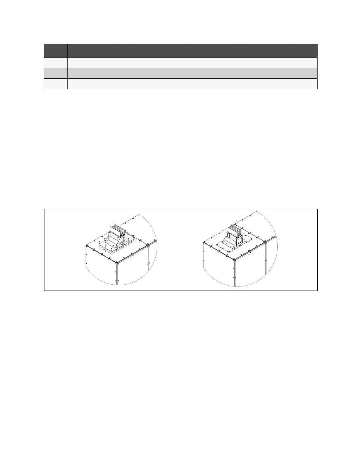
The below images illustrate proper installation of an Vertiv panel flange, using M8 hardware. Front, side, and/or rear covers
may need to be removed to access hardware on the underside of the gland plate. Apply torque settings for hardware as set
forth in Table 7.1 on page43 . Size, amperage, material, and phasing orientation of the flange are determined on a per project
basis. Joining busway sections together should be done so by following the busbar installation manual provided by the
manufacturer.
Figure 4.34 Typical Installation of a Panel Flange
If a busway flange is required on a type 3R unit, then the sealing of the flange is critical. Once the internal connections are
completed, the installer is solely responsible for sealing the connection between the flange and switchboard. It is up to the
installer to use gasket or properly rated silicone to ensure a liquid tight seal. If the connection between the flange and
switchboard is insufficient, the panel may leak and cause damage.
NOTE: Vertiv takes no liability for the panel leaking based on the installation of the flange.
38 Proprietary and Confidential ©2024 Vertiv Group Corp. 4 Installation
Vertiv™ UL891 Switchboard Installer/User Guide