4.4 Joining Sections
Hardware for joining the switchboards is provided by the manufacturer. The standard hardware provided is an M8x12 mm
socket head screw. There will be a total of 27 to 30 installed per split, depending on the depth of the panel. A cluster of holes
are provided on the frame of each switchboard section for this purpose (see Figure 4.5 below ). The holes are located every
7.6 in. in the front, top, and rear of each section. A minimum of 7 to 8 locations will need the joining screws to pull the sections
together. Figure 4.6 on the facing page shows the typical locations for joining the splits together.
While maintaining the level and alignment of the structures, apply torque of 10Nm / 7ft-lbs. If the switchboard is outdoor, make
sure the cap is also installed at each split, as well as the front joining hardware (See Figure 4.7 on page26 ). Hardware for the
cap and front joining should be torqued to the values set forth in Table 7.1 on page43 . Once the switchboard sections are
attached, visually inspect, and verify the boards are free of any foreign objects, and that necessary clearances for live parts are
still maintained.
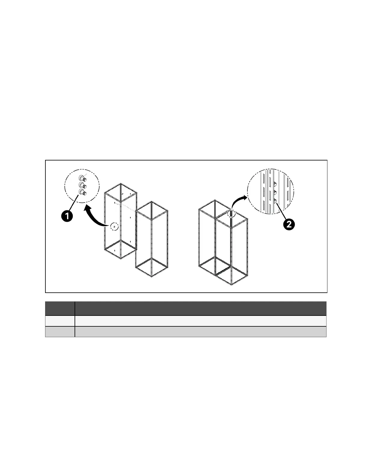
Figure 4.5 Typical Frame Joining
Item Description
1 Joining Screw
2 Joining screw threads into both frame
24 Proprietary and Confidential ©2024 Vertiv Group Corp. 4 Installation
Vertiv™ UL891 Switchboard Installer/User Guide