Figure 2.13 Typical Provision for Double Stacked Front/Rear Access and Bottom Incoming Customer Cable
Connections
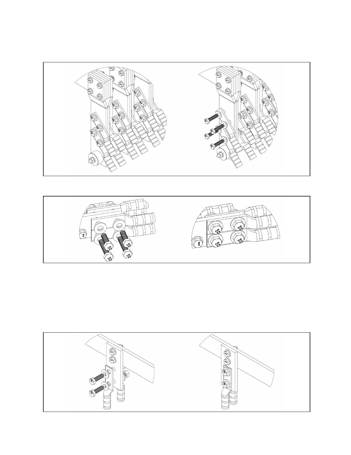
Figure 2.14 Typical Provision for MCCB Customer Cable Connections
2.6 Typical Ground Layout
The ground is a system that runs the complete length of any switchboard. There are taps periodically throughout each
switchboard for tapping off for field terminations.
Below are typical arrangements of ground cable provisions per switchboard configuration.
Figure 2.15 Typical Ground Dropper Arrangement with Provisions for up to two (2) Compression Lugs
8 Proprietary and Confidential ©2024 Vertiv Group Corp. 2 Introduction
Vertiv™ UL891 Switchboard Installer/User Guide