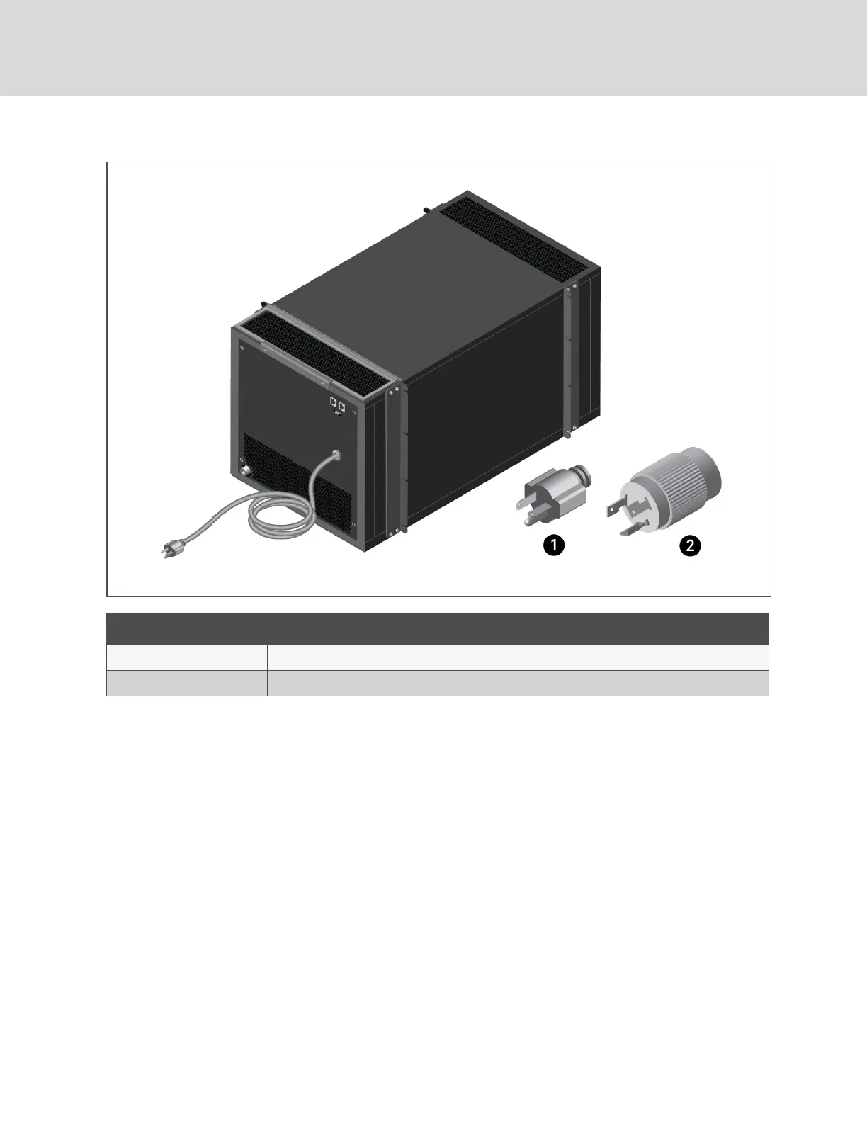
Figure 4.5 Power Cord and Plug
Item Description
1 5-20P plug for VRC100
2 L6-20P plug for VRC101
4.5 Monitoring and Display Connections
The rear panel of the unit includes connectors for third-party monitoring systems and for the display
controller, see Figure 4.6 on the facing page. Table 4.1 on the facing page, describes the pin-out of
each RJ-45 connector.
NOTE: An optional SIC-card monitoring kit is available from Vertiv™ for one of the remote-monitoring
connections. Contact your Vertiv™ representative for additional information.
To connect the display controller:
Connect the cable from the display unit to the connector on the rear of the unit, see Figure 4.6 on the
facing page.
Vertiv™ | VRC Installer/User Guide
18
 Loading...


