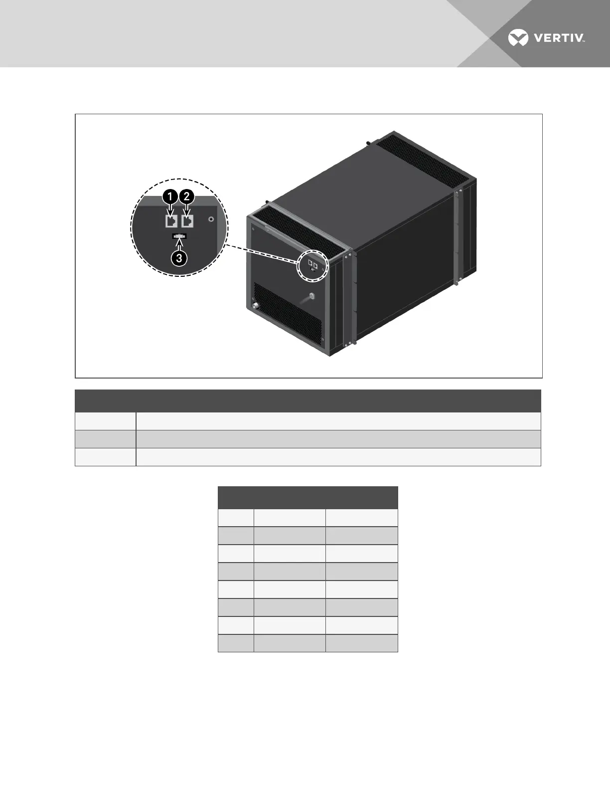
Figure 4.6 Monitoring and Display Connectors
Item Description
1 RS485-1. RJ-45 port, see Table 4.1 below, for pin-out
2 RS485-2. RJ-45 port, see Table 4.1 below, for pin-out
3 Display connector
Pin RS485-1 RS485-2
1 12V NC
2 12V NC
3 NC NC
4 GND GND
5 GND GND
6 NC NC
7 D+ D+
8 D– D–
Table 4.1 Communication Port Pin-out
4 Installation
19
 Loading...


