Last update: 2022/04/01 18:06 slice:qt https://www.vescent.com/manuals/doku.php?id=slice:qt
https://www.vescent.com/manuals/ Printed on 2022/04/05 13:27
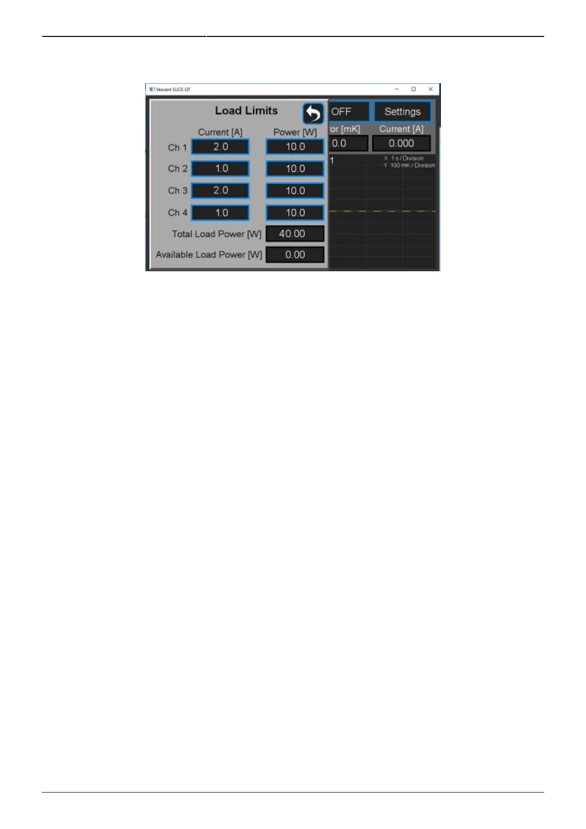
the Home screen, select CH X > Settings > Load Limits and the screen shown in figure 23 will appear.
Fig. 23: Screen for adjustment of control power capacity
Transducer and Thermistor
To set the properties of the transducer (TEC or heater) and thermistor for an individual channel from
the Home screen, touch CH X > Settings > Plant. The menu in figure 24 will appear. Select
TEC/Bipolar (as seen) or by touching TEC/Bipolar, select Heater/Unipolar.
From this screen, it is also possible to set the polarity of the TEC. Touch Polarity Positive/Polarity
Negative to toggle between the two states. The polarity is already set correctly to NEGATIVE for use
with NTC thermistors.
The thermistor data has been configured at the factory for a typical NTC thermistor that is 10 kΩ at
25°C. Only NTC (Negative Thermal Coefficient) thermistors can be used. You can enter a new Beta
value, reference temperature, and resistance value and the Steinhart-Hart constants will be
calculated automatically or vice versa.
NOTE: The SLICE-QTC can achieve sub-millikelvin stabilities over a very wide set point temperature
range. For most applications working near room temperature, an NTC thermistor with a nominal value
of 10 kΩ at 25°C will work fine. For temperatures far from room temperature, best results will occur
by choosing a thermistor that has a resistance of 10 kΩ at your desired set point temperature. The
input bridge circuitry is configured to have maximum sensitivity at a 10-kΩ resistance.