2022/04/05 13:27 19/26 SLICE-QTC Four-Channel Temperature Controller
Product Manuals - https://www.vescent.com/manuals/
Feedforward
This mode allows a feedforward signal to be summed into the output of the PID loop filter. The
feedforward signal current is related to the input voltage Vin by: Feedforward Current [A] = Gain[A/V]
x Vin + Offset[A]. Touch the Settings icon to the right of the channel selection to adjust the Gain and
Offset.
Choice Comment
Off Value not read
Slow Servo Input
Input is routed through an integrator and
then used to control the set point
External Set Point
Externally control the set point
temperature
External Error
Input
Alternate input path for error signal
(bypasses wheatstone bridge)
Feed Forward Sums input value with loop filter output.
Tab. 7: Front-panel input signals
Output Channels 1 & 2
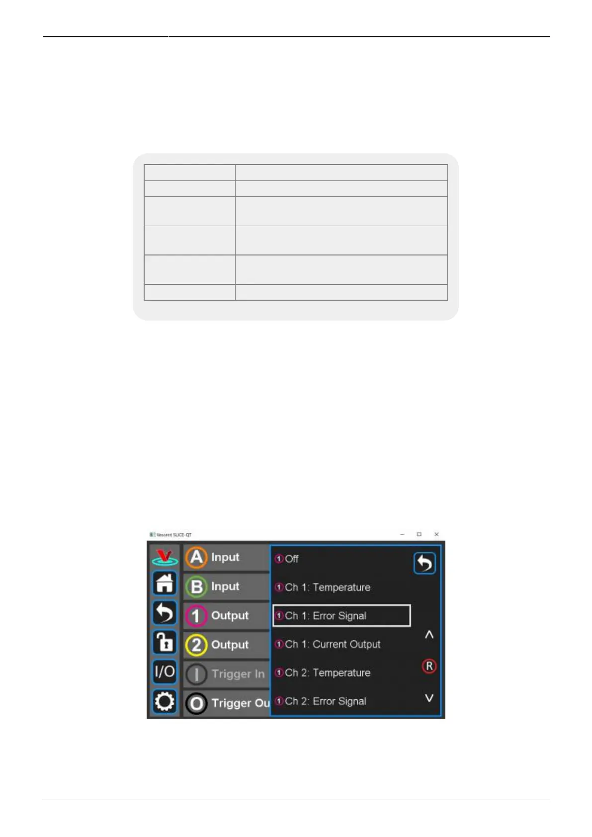
Similarly, you can program the output signals for the Output Channels 1 and 2. For each channel, the
actual (measured) temperature, the temperature error, or the current output can be chosen as the
output signal. For instance, if you select Channel 1 Output from figure 27 you will be presented with
figure 29. You can choose any value from table 8 to be delivered to the Channel 1 Output output on
the front panel. Touch the Settings icon to the right of the channel selection to adjust the Gain and
Offset for these output signals as in figure 30. When porting the Temperature of a given loop to an
Output, setting the Gain equal to 0.1 V/°C and the offset to 0 V will give a convenient 2 V output at
20°C.
Fig. 29: Programming the output on Channel 1 Output