DGT / DGT60 / DGTQ / DGTP
45
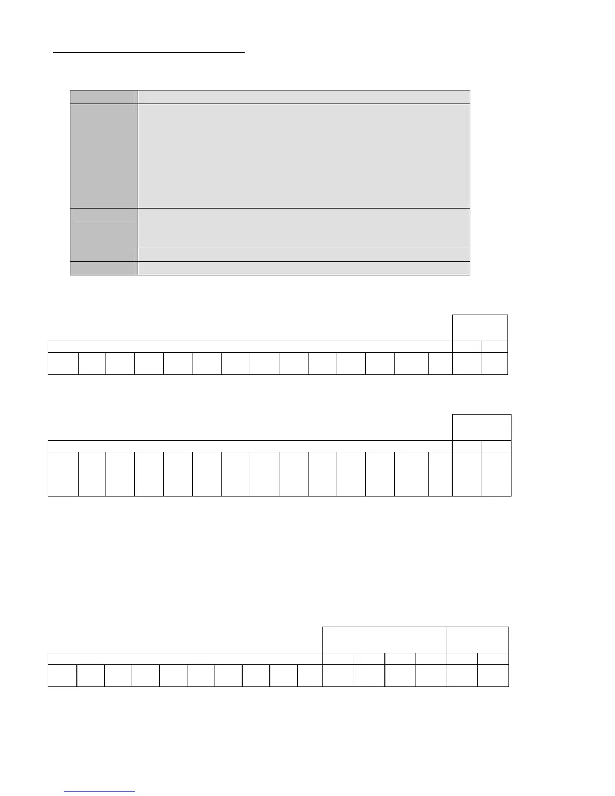
Enabling/disabling of the output command:
Sintax
Format <ESC><II> OUTPNVVVV <STX>
Parameters - N = output number (expressed in hexadecimals)
- 0 to activate simultaneously all the outputs
- from 1 to 2 to identify the single output which one wants to enable
(from 1 to 6 with the DGTQ model).
- VVVV = enabling/disabling code;
- for the single output, V = 0000 disabled, while V = 0001 enabled.
- for all the outputs (in other words N = 0), the value identifies the
outputs to be enabled (expressed in hexadecimals).
Answer <ESC><II>OK<STX>
The answer does not imply that the command has been made on the
output or all the set outputs.
Example <ESC>01OUTP00003<STX>
Result Configuration of the outputs (see the following explanation)
DGT and DGT60 models
A bit is ascribed to each output:
Board
outputs
Bit not managed RL 2 RL 1
Bit
15
Bit
14
Bit
13
Bit
12
Bit
11
Bit
10
Bit
9
Bit
8
Bit
7
Bit
6
Bit
5
Bit
4
Bit
3
Bit
2
Bit
1
Bit
0
The bit at 1 is interpreted as active output, while the bit at 0 as disabled output.
If, for example, one wants to enable simultaneously the R1 and R2 outputs, the binary combination will be
Board
outputs
Bit not managed RL 2 RL 1
Bit
15
0
Bit
14
0
Bit
13
0
Bit
12
0
Bit
11
0
Bit
10
0
Bit
9
0
Bit
8
0
Bit
7
0
Bit
6
0
Bit
5
0
Bit
4
0
Bit
3
0
Bit
2
0
Bit
1
1
Bit
0
1
Which, in hexadecimals, corresponds to the number 0003; therefore the command will be OUTP00003 + CR + LF.
NOTES:
- The set point enabling command does not work neither in the set-up environment nor in the weighing phase; if the
setpoint mode has been selected and the output function is different than "nonE". (rif. output step, FunC parameter).
- No output is ascribed to the bits from 2 to 15 and are fixed at zero.
DGTQ model
A bit is ascribed to each output:
Expansion outputs
(optional)
Board
outputs
Bit not managed OUT6 OUT5 OUT4 OUT3 OUT2 OUT1
Bit
15
Bit
14
Bit
13
Bit
12
Bit
11
Bit
10
Bit
9
Bit
8
Bit
7
Bit
6
Bit
5
Bit
4
Bit
3
Bit
2
Bit
1
Bit
0
The bit at 1 is interpreted as active output, while the bit at 0 as disabled output.
If, for example, one wants to enable simultaneously the OUT6, OUT4 and OUT2 outputs, the binary combination will
be