Installation
2-9
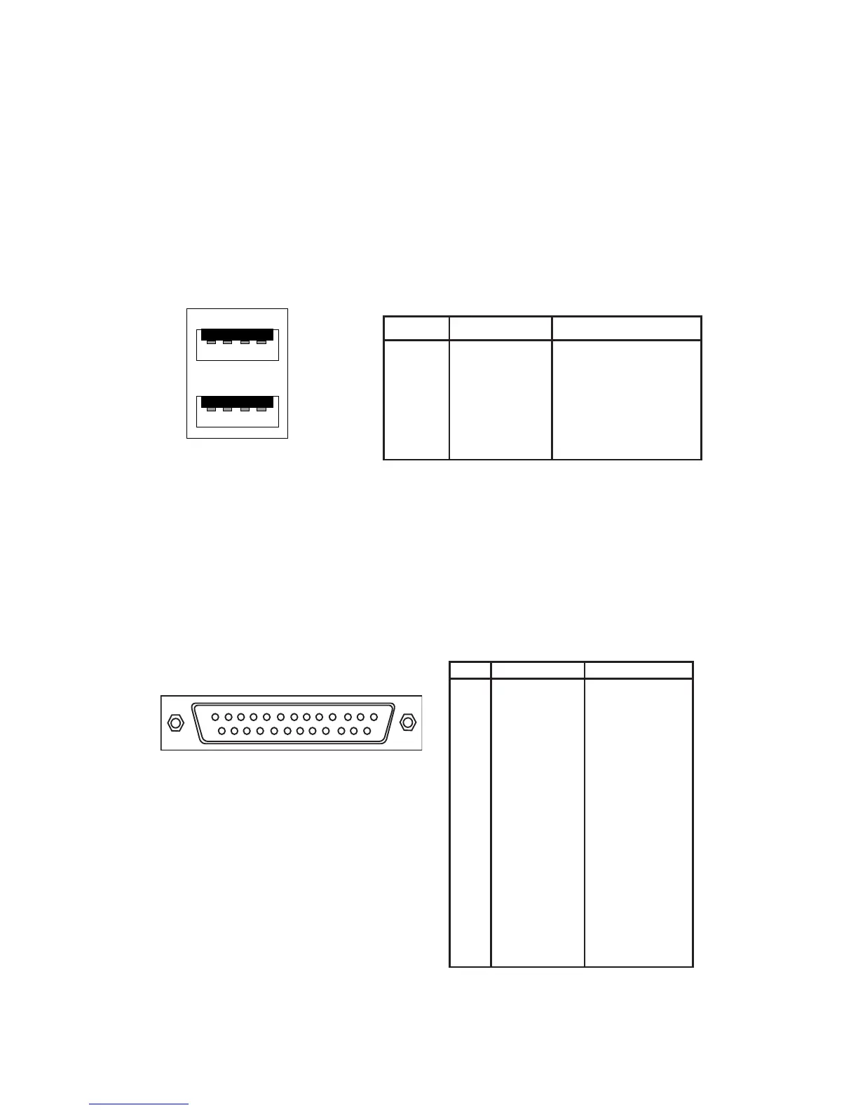
USB Port Connectors
The VIA P4MA PRO mainboard provides 2 USB 2.0 ports (plus 1 pin-headers
for up to 2 additional USB 2.0 connections; see 2-17). USB-compatible devices
can be plugged directly into these ports.
Pin Definition
USB Ports
1 2 3 4
5 6 7 8
Parallel Port Connector: LPT1
The mainboard provides a 25-pin female connector for LPT (parallel port). A
parallel port is a standard printer port that supports Enhanced Parallel Port
(EPP) and Extended Capabilities Parallel Port (ECP) modes.
13
1
1425
PIN SIGNAL DESCRIPTION
1 STROBE Strobe
2 DATA0 Data0
3 DATA1 Data1
4 DATA2 Data2
5 DATA3 Data3
6 DATA4 Data4
7 DATA5 Data5
8 DATA6 Data6
9 DATA7 Data7
10 ACK# Acknowledge
11 BUSY Busy
12 PE Paper End
13 SELECT Select
14 AUTO FEED# Automatic Feed
15 ERR# Error
16 INIT# Initialize Printer
17 SLIN# Select In
18 GND Ground
19 GND Ground
20 GND Ground
21 GND Ground
22 GND Ground
23 GND Ground
24 GND Ground
25 GND Ground
Pin Definition
PIN SIGNAL DESCRIPTION
1 VCC +5V
2 -Data 0 Negative Data Channel 0
3 +Data 0 Positive Data Channel 0
4 GND Ground
5. VCC +5V
6. -Data 1 Negative Data Channel 1
7. +Data 1 Positive Data Channel 1
8. GND Ground