Chapter 2
2-10
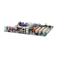
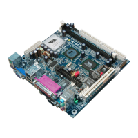
Serial Port Connectors: COM 1
The mainboard offers one 9-pin male Serial Port connector (COM 1) . You can
attach a serial mouse or other serial devices directly to this port.
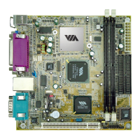
MIDI/Game Connector
You can connect a joystick or game pad
to this connector.
Pin Definition
1 2 3 4 5
6 7 8 9
9-Pin Male DIN Connectors
PIN SIGNAL DESCRIPTION
1 DCD Data Carry Detect
2 SIN Serial In or Receive Data
3 SOUT Serial Out or Transmit Data
4 DTR Data Terminal Ready
5. GND Ground
6. DSR Data Set Ready
7. RTS Request To Send
8. CTS Clear To Send
9. RI Ring Indicate
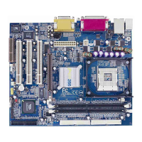
Audio Port Connectors
Line-Out is a connector for speakers
or headphones. The Line-In connec-
tor can be used for an external CD
player, tape player, or other audio
devices. The Mic-In connector is for
connecting microphones. Please note
when 6-channel applications are used,
all three connectors become output
connectors. Line-Out becomes Front
L/R; Line-In becomes Rear L/R; Mic-
In becomes Center/Sub.
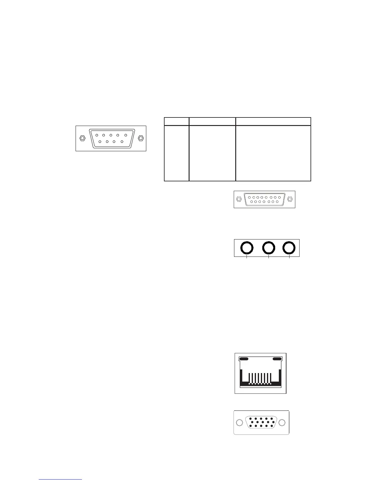
RJ-45 NIC Port
The mainboard provides one standard
RJ-45 port for connection to the Local
Area Network (LAN). You can connect
a network cable to the LAN port.
VGA Out
A DB-15 pin female connector that con-
nects to a VGA monitor.
1/8” Stereo Audio Connectors
Line Out MICLine In
L/R
L/R
Rear
Front
Sub
Center
(2 Channel)
(6 Channel)