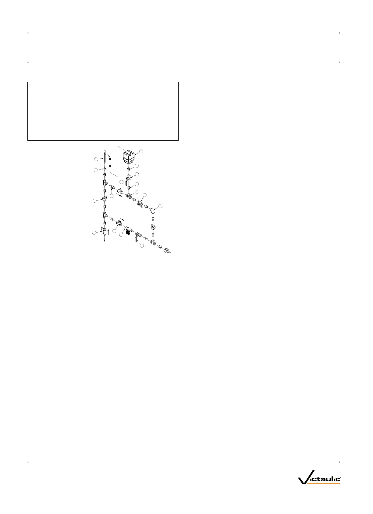
VICTAULICSERIES757PAIRMAINTENANCETRIMASSEMBLY
(AMTA)WITHPRESSURESWITCHOPTION
NOTICE
VictaulicrecommendsamaximumoftwoSeries768FireLock•
NXTDryValvesperSeries757PAMTAwithPressureSwitch.
RefertotheI-757PAirMaintenanceTrimAssemblywith•
PressureSwitchInstallationInstructions,suppliedwiththe
product,forcompleteinstallation,electrical,andpressure
switchadjustmentinformation.
5
2
12
7
8
15
10
16
9
6
4
1
13
3
14
11
TO
SYSTEM
FROM
COMPRESSOR
Bill of Materials
Item Qty. Description
1 1 Restrictor (½-inch NPT)
2 1 Strainer (½-inch NPT)
3 1 Swing Check (½-inch NPT)
4 1 Slow-Fill Ball Valve
(Normally Open)
5 1 Spring-Loaded, Soft-Seated
Check Valve
6 1 Pressure Switch
7 2 Compression Fitting, Straight
(¼-inch NPT x ¼-inch Tube)
8 1 Copper Tubing (¼-inch OD)
9 11 Close Nipple
(½-inch NPT x 1.13)
10 1 Nipple (½-inch NPT x 4.00)
11 1 90° Female Elbow (½-inch NPT
12 4 Female Tee (½-inch NPT)
13 3 Union (½-inch NPT)
14 2 Reducing Bushing
(½-inch NPT x ¼-inch NPT)
15 1 Fast-Fill Ball Valve
(Normally Closed)
16 1 Pressure Switch Isolation Ball
Valve (Normally Open -
Lockable)
COMPRESSORREQUIREMENTSANDSETTINGSFORSERIES768
FIRELOCKNXTDRYVALVESINSTALLEDWITHSERIES746-LPA
DRY ACCELERATORS
Set the air regulator of the Series 757 Regulated AMTA to a minimum of
13 psi/90 kPa/0.9 Bar.
FORVdSAPPROVEDVALVESONLY: The minimum air pressure for
Series 768 FireLock NXT Dry Valves installed with Series 746-LPA Dry
Accelerators shall be 16 psi/110 kPa/1.1 Bar. The maximum air pressure
shall be 19 psi/130 kPa/1.3 Bar.
TheSeries757PAirMaintenanceTrimAssemblywithPressure
SwitchMUSTNOTbeusedonaSeries768FireLockNXTDryValve
installedwithaSeries746-LPADryAccelerator,unlessatankandair
regulatorareadded.
In the event a compressor becomes inoperative, a properly sized tank-
mounted air compressor provides the greatest protection for systems
installed with a Series 746-LPA Dry Accelerator. In this situation, air
can be supplied continuously to the sprinkler system for an extended
time period. NOTE: The Series 757 Regulated AMTA should be used
with a tank-mounted air compressor to supply air to a Series 768
FireLock NXT Dry Valve when the Series 746-LPA Dry Accelerator
is used. The use of an air regulator with a base or riser-mounted air
compressor could cause short cycling, resulting in premature wear of
the compressor.
The air regulator of the Series 757 Regulated AMTA is a relief-type
design. Any pressure in the system that is above the set point of the air
regulator will be released. Therefore, charging the air regulator above
the set point could cause premature operation of a valve installed with a
Series 746-LPA Dry Accelerator.
SETTINGSFORAIRSUPERVISORYPRESSURESWITCHESAND
ALARMPRESSURESWITCHES
1. Air supervisory pressure switches are required for dry systems and
must be set according to the following notes. NOTE: Switches for
Vic-Quick Risers are pre-set at the factory.
1a. Wire the air supervisory pressure switches to activate a
low-pressure alarm signal. NOTE: In addition, the local
authority having jurisdiction may require a high-pressure
alarm. Contact the local authority having jurisdiction for this
requirement.
1b. Set the air supervisory pressure switches to activate at
2 – 4 psi/14 – 28 kPa/0.1 – 0.3 Bar below the minimum air
pressure required (but not lower than 10 psi/69 kPa/0.7 Bar).
1c. Wire the alarm pressure switch to activate a water flow alarm.
1d. Set the alarm pressure switch to activate on a pressure rise of
4 – 8 psi/28 – 55 kPa/0.3 – 0.6 Bar.
REMOTESYSTEMTESTVALVEREQUIREMENTS
The remote system test valve (inspector’s test connection) should
contain a UL Listed and/or FM Approved valve (normally closed), which
can be opened to simulate the operation of a sprinkler.
The remote system test valve (inspector’s test connection) should be
located at the most hydraulically demanding location in the release
system. NOTE: Multiple restrictions on the remote system test valve
(inspector’s test connection) may slow the air decay rate and cause the
system to respond slower than required.
The remote system test valve (inspector’s test connection) should
terminate with an orifice equal to the smallest orifice in the releasing
system.
The remote system test valve (inspector’s test connection) is used to
ensure that water reaches the most remote part of the system within 60
seconds.
I-768_10
FireLockNXT™DryValve
SERIES768
I-768
INSTALLATION,MAINTENANCE,ANDTESTINGMANUAL
www.victaulic.com
VICTAULIC IS A REGISTERED TRADEMARK OF VICTAULIC COMPANY. © 2007 VICTAULIC COMPANY. ALL RIGHTS RESERVED. PRINTED IN THE USA.
REV_D

 Loading...