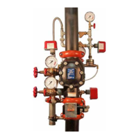
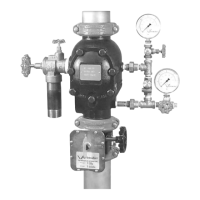
INTRODUCTION
The following instructions are a guide for proper installation of Victaulic Series 768 FireLock NXT Dry Valves. These instructions involve pipe that is
properly prepared and grooved in accordance with current Victaulic specifications.
NOTICE
Drawingsand/orpicturesinthismanualmaybeexaggeratedforclarity.•
Thisproductandthisinstallation,maintenance,andtestingmanualcontaintrademarks,copyrights,and/orpatentedfeaturesthatarethe•
exclusivepropertyofVictaulic.
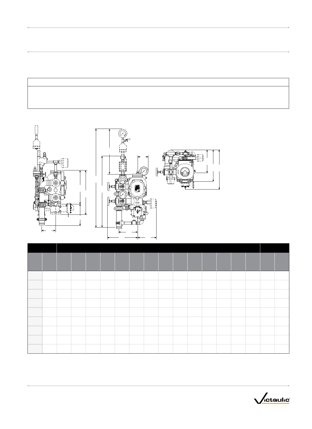
TRIMDIMENSIONS
THE4-INCH/114.3-MMCONFIGURATIONISSHOWNBELOW.1–2-INCH/48.3–60.3-MMCONFIGURATIONSCONTAIN-INCH/19-MMDRAINVALVES.
2–3-INCH/73.0–88.9-MMCONFIGURATIONSCONTAIN1-INCH/31-MMDRAINVALVES.4–8-INCH/114.3–219.1-MMCONFIGURATIONSCONTAIN2-INCH/50-MMDRAINVALVES.
A
J
*A1
B
*B1
G
F
D
*D1
C
Full Open
K
*E1
E
H
Size Dimensions–inches/mm
Aprx.WeightEa.
lbs/kg
Nominal
Size
inches
mm
Actual
Outside
Diameter
inches
mm A A1* B B1* C D D1* E E1* F G H J K
Without
Trim
With
Trim
1 ½
40
1.900
48.3
9.00
228.60
16.43
417. 32
27. 2 5
692
39.50
1003
13.75
349
16.00
406
—
5.25
133
8.50
215
9.50
241
21.25
539
3.04
77.21
9.17
232.91
6.98
17 7.29
16.7
7. 6
43.0
19.5
2
50
2.375
60.3
9.00
228.60
16.43
417. 32
27. 2 5
692
39.50
1003
13.75
349
16.00
406
—
5.25
133
8.50
215
9.50
241
21.25
539
3.04
77.21
9.17
232.91
6.98
17 7.29
17. 0
7.7
43.0
19.5
2 ½
65
2.875
73.0
12.61
320.29
16.50
419.10
32.25
819
44.25
112 3
13.50
342
16.00
406
17. 50
444
5.25
133
9.00
228
9.25
234
21.25
539
3.90
99.06
10.50
266.70
6.93
176.02
41.0
18.7
65.0
29.5
76.1 mm
3.000
76.1
12.61
320.29
16.50
419.10
32.25
819
44.25
112 3
13.50
342
16.00
406
17. 50
444
5.25
133
9.00
228
9.25
234
21.25
539
3.90
99.06
10.50
266.70
6.93
176.02
41.0
18.7
65.0
29.5
3
80
3.500
88.9
12.61
320.29
16.50
419.10
32.25
819
44.25
112 3
13.50
342
16.00
406
17. 50
444
5.25
133
9.00
228
9.25
234
21.25
539
3.90
99.06
10.50
266.70
6.93
176.02
41.0
18.7
65.0
29.5
4
100
4.500
114 . 3
15.03
381.76
19.78
502.41
33.50
850
45.50
115 5
15.00
381
15.75
400
20.50
520
5.25
133
9.00
228
10.75
273
21.00
533
6.25
158.75
9.62
244.34
8.46
214.88
59.0
26.7
95.0
43.0
165.1 mm
6.500
165.1
16.00
406.40
22.00
558.80
34.00
863
46.00
116 8
15.50
393
17. 0 0
431
22.00
558
5.25
133
8.50
215
11. 5 0
292
20.50
520
6.20
15 7.4 8
9.62
244.34
8.84
224.53
80.0
36.2
116 . 0
52.6
6
150
6.625
168.3
16.00
406.40
22.00
558.80
34.00
863
46.00
116 8
15.50
393
17. 0 0
431
22.00
558
5.25
133
8.50
215
11. 5 0
292
20.50
520
6.20
15 7.4 8
9.62
244.34
8.84
224.53
80.0
36.2
116 . 0
52.6
8
200
8.625
219.1
17. 50
444.50
22.94
582.67
33.50
850
45.50
115 5
16.75
425
20.00
508
25.25
641
6.25
158
8.75
222
12.75
323
18.50
469
6.05
153.67
9.40
238.76
10.21
259.33
122.0
55.3
158.0
71.6
NOTES:
The “A” dimension coupling is not shown in order to clarify dimensional callouts.
Components shown as dotted lines denote optional equipment.
* Measurements denoted with an asterisk take optional equipment into account.
Optional drain connection kit is shown for reference and takeout dimensions.
NOTES FOR EUROPEAN TRIM:
For European trim, add 3.75 inches/95 mm to the D, D1, and F dimensions to
account for the additional water motor alarm shutoff valve.
For 1 ½-inch/48.3-mm European trim, add 14.10 inches/358.14 mm to the “A”
dimension to account for the two Victaulic rigid couplings, the water supply
main control valve, and the grooved x grooved nipple with outlet hole.
For 2-inch/60.3-mm European trim, add 14.21 inches/360.93 mm to the “A”
dimension to account for the two Victaulic rigid couplings, the water supply
main control valve, and the grooved x grooved nipple with outlet hole.
I-768_3
FireLockNXT™DryValve
SERIES768
I-768INSTALLATION,MAINTENANCE,ANDTESTINGMANUAL
www.victaulic.com
VICTAULIC IS A REGISTERED TRADEMARK OF VICTAULIC COMPANY. © 2007 VICTAULIC COMPANY. ALL RIGHTS RESERVED. PRINTED IN THE USA.
REV_D

 Loading...