IMPORTANTINSTALLATIONINFORMATION
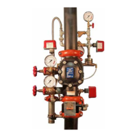
1. For proper operation and approval, the Series 768 FireLock NXT
Dry Valve must be installed in accordance with the specific trim
diagrams included with the shipment. NOTE: Victaulic provides
specific trim diagrams for installations involving a Series 746-LPA
Dry Accelerator.
2. Before installing the Series 768 FireLock NXT Dry Valve, flush the
water supply piping thoroughly to remove all foreign material.
3. Series 768 FireLock NXT Dry Valves MUST NOT be located in an
area where the valve can be exposed to freezing temperatures. In
addition, the Series 768 FireLock NXT Dry Valve MUST NOT be
located in an area where physical damage may occur.
4. It is the system designer’s responsibility to confirm material
compatibility of the Series 768 FireLock NXT Dry Valve, trim,
and associated accessories when a corrosive environment or
contaminated water is present.
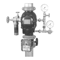
5. SERIES768FIRELOCKNXTDRYVALVESMUSTBE
INSTALLEDONLYINTHEVERTICALPOSITIONWITHTHE
ARROWONTHEBODYPOINTINGUPWARD.
6. Air or nitrogen supply to the dry piping system must be clean, dry,
and oil-free.
7. Air supplies must be regulated, restricted, and continuous.
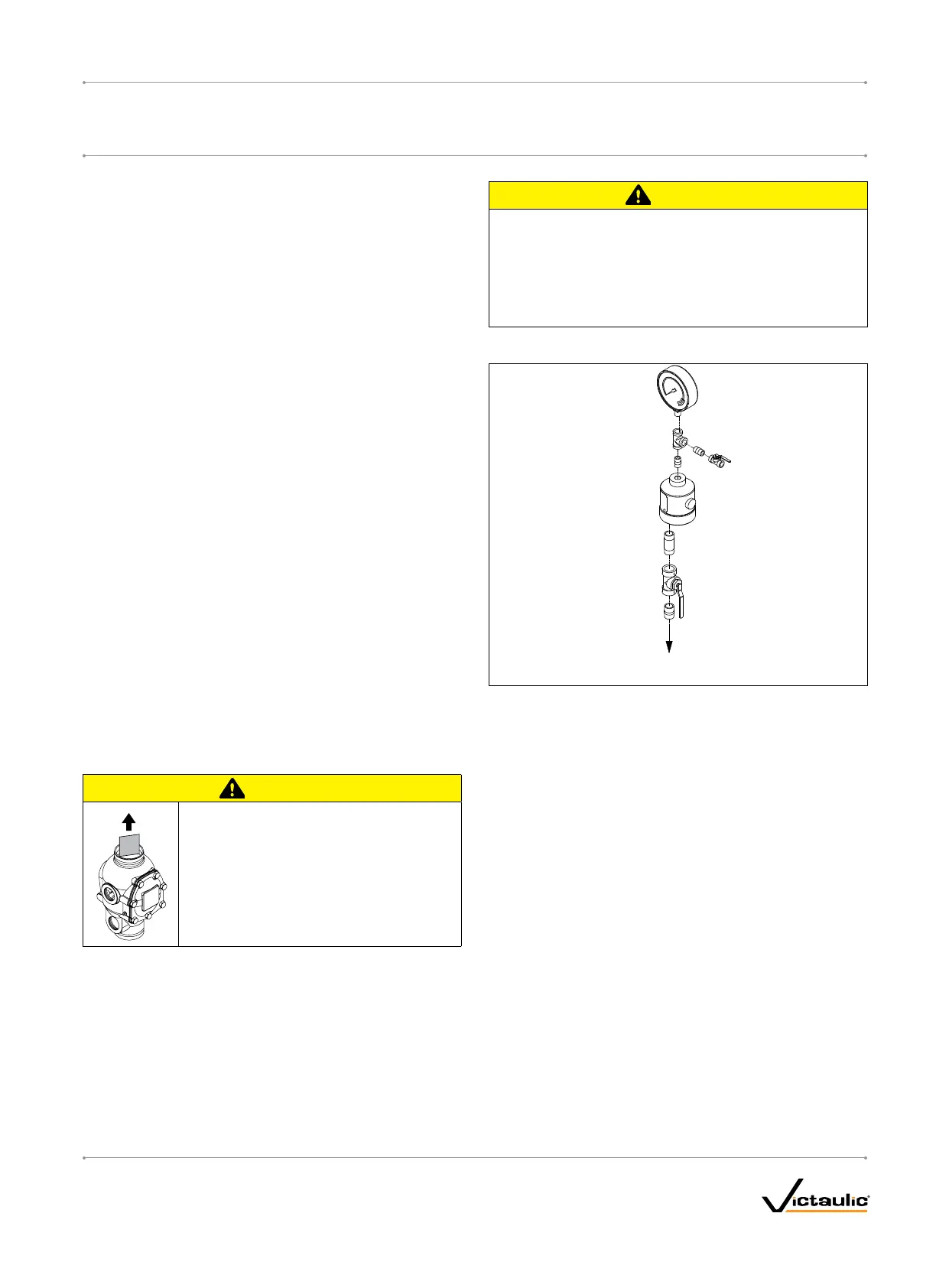
8. When an uninterruptible water flow alarm is required, Victaulic
recommends the use of a low-pressure alarm installed on the
diaphragm charge line downstream of the strainer/check restrictor.
Another option is to install a Series 75B Supplemental Alarm
Device.
9. Per NFPA 13 requirements, piping must be pitched so that
systems can drain properly. For areas that are subject to high
levels of condensation, or where piping is not properly pitched, an
optional Series 75D Water Column Device kit is available to assist
in a utomatically draining water out of the riser.
VALVE/TRIMINSTALLATION
1. Make sure the trim drawing matches the system’s requirements.
CAUTION
Makesurethefoamspacerisremovedfrom•
insidethevalvebodybeforeattemptingto
installthevalve.
Failuretofollowthisinstructioncouldcause
impropervalveoperation,resultinginpersonal
injuryand/orpropertydamage.
2. Remove all plastic caps and foam spacers from the valve.
3. Apply a small amount of pipe joint compound or Teflon* tape to
the external threads of all threaded pipe connections. DO NOT get
any tape, compound, or other foreign material into the valve body,
pipe nipples, or valve openings.
CAUTION
Makesurenoforeignmaterialgetsintothevalvebody,pipe•
nipples,orvalveopenings.
IfusinganymaterialotherthanTeflontape,useextracaution•
sothatnomaterialgetsintothetrim.
Failuretofollowtheseinstructionscouldcauseimpropervalve
operation,resultinginpersonalinjuryand/orpropertydamage.
4. Install the valve, trim, and accessories per the trim drawing.
TO ACTUATOR
TRIM
5. FORVALVESINSTALLEDWITHASERIES746-LPADRY
ACCELERATOR:Make sure the Series 746-LPA Dry Accelerator is
installed in accordance with the trim drawing provided. The end
with the vent seal “button” must be installed facing down (toward
the trim, as shown above).
6. Supply pressure to the diaphragm charge line by providing an
uninterrupted source of water from upstream of the main control
valve.
* Teflon is a registered trademark of the DuPont Company
I-768_11
FireLockNXT™DryValve
SERIES768
I-768INSTALLATION,MAINTENANCE,ANDTESTINGMANUAL
www.victaulic.com
VICTAULIC IS A REGISTERED TRADEMARK OF VICTAULIC COMPANY. © 2007 VICTAULIC COMPANY. ALL RIGHTS RESERVED. PRINTED IN THE USA.
REV_D

 Loading...