SECTIONVIEWDRAWINGANDDESCRIPTION–
SERIES776LOW-PRESSUREACTUATOR
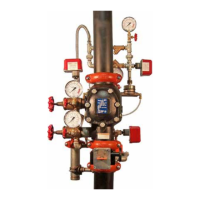
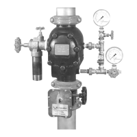
The Series 776 Low-Pressure Actuator is located in the trim of Series
Since the area of the lower diaphragm (exposed to water pressure in
768 FireLock NXT Dry Valves and acts as the trigger for these systems.
the middle chamber) is greater than the area of the lower chamber, the
lower chamber seals off. Water does not flow to the outlet of the low-
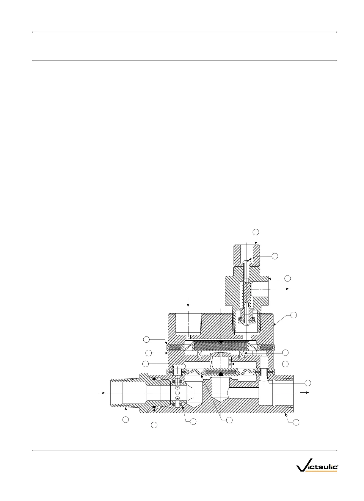
Diaphragms separate the low-pressure actuator into three chambers.
pressure actuator, and the supply water pressure creates the water seal.
The upper air chamber controls activation, while the middle and lower
chambers act as the water valve.
When system air pressure decays to 7 psi/48 kPa/0.5 Bar, the force
exerted by the compression spring in the Auto Vent is greater than the
During setup, system air is applied to the upper chamber of the low-
force exerted by air in the upper chamber. The Auto Vent opens, and all
pressure actuator. When the Auto Vent Sleeve of the low-pressure
air pressure in the upper chamber evacuates.
actuator is pulled up, the upper chamber manually sets. Air pressure in
the upper chamber holds the Auto Vent closed, while it exerts force on
The upper diaphragm releases water pressure in the middle chamber
the water seal of the middle chamber.
of the low-pressure actuator, which allows the lower diaphragm to lift
and water to flow from the inlet to the outlet. This flow of water releases
When the diaphragm charge line is opened, water enters the lower
pressure from the diaphragm charge line of the Series 768 FireLock
chamber of the low-pressure actuator. Water that enters the low-
NXT Dry Valve, thus allowing the diaphragm to retract. The clapper
pressure actuator flows to the middle chamber through the inlet eyelet,
opens, and water flows into the sprinkler system.
which is pressurized by system air pressure in the upper chamber.
VENT TO ATMOSPHERE
INLET
AIR IN
OUTLET
1
2
3
4
5
6
7
8
9
10
11
12
13
14
15
Exaggerated for Clarity
BillofMaterials
1 Auto Vent Sleeve 9 Lower Diaphragm Assembly
2 Auto Vent Screw 10 Strainer Screen (Replaceable)
3 Auto Vent Assembly 11 Strainer O-Ring Seal
4 Upper Chamber 12 Strainer Assembly
5 Upper Diaphragm Wave Spring 13 Inlet Eyelet
6 Lower Diaphragm Wave Spring 14 Middle Chamber
7 Outlet Eyelet 15 Upper Diaphragm Assembly
8 Lower Chamber
I-768_7
FireLockNXT™DryValve
SERIES768
I-768INSTALLATION,MAINTENANCE,ANDTESTINGMANUAL
www.victaulic.com
VICTAULIC IS A REGISTERED TRADEMARK OF VICTAULIC COMPANY. © 2007 VICTAULIC COMPANY. ALL RIGHTS RESERVED. PRINTED IN THE USA.
REV_D

 Loading...