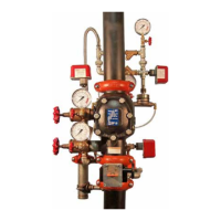
7. Open the remote system test valve (inspector’s test connection) or
the system main drain valve to simulate an open sprinkler. NOTE:
The system main drain valve is shown above.
8. Record the system air pressure when the valve operates, along
with any other information required by the authority having
jurisdiction.
9. Confirm that the diaphragm charge line’s pressure drops to zero
and that water is flowing through the auto drain to the drip cup.
Water Supply Main
Control Valve
10. Close the water supply main control valve fully.
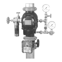
11. Close the remote system test valve (inspector’s test connection) or
the system main drain valve. NOTE: The system main drain valve
is shown above.
12. SHUTOFFTHEAIRSUPPLY.
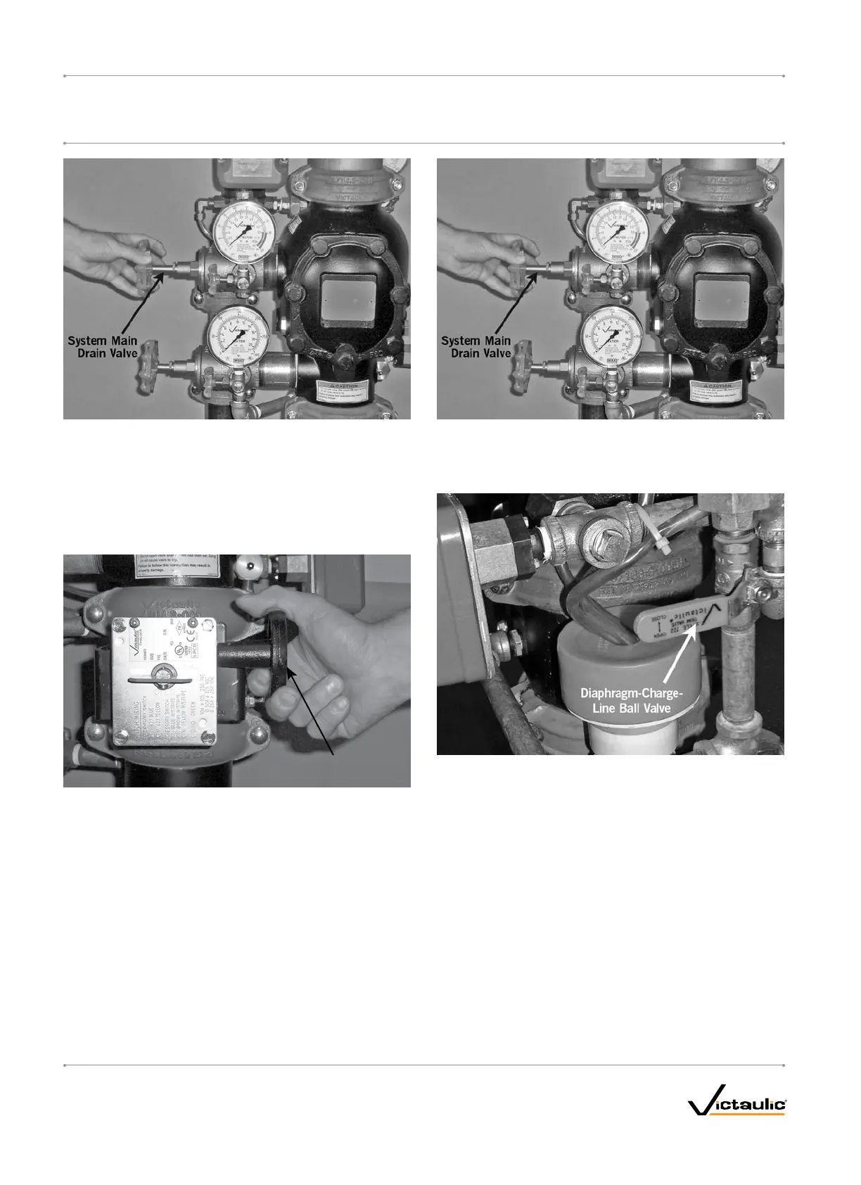
13. Close the diaphragm-charge-line ball valve.
14. Perform all steps in the “Placing the System in Service” section.
I-768_26
FireLockNXT™DryValve
SERIES768
I-768
INSTALLATION,MAINTENANCE,ANDTESTINGMANUAL
www.victaulic.com
VICTAULIC IS A REGISTERED TRADEMARK OF VICTAULIC COMPANY. © 2007 VICTAULIC COMPANY. ALL RIGHTS RESERVED. PRINTED IN THE USA.
REV_D

 Loading...