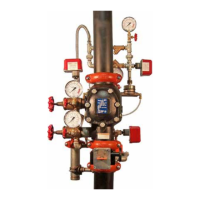
7. Close the diaphragm-charge-line ball valve.
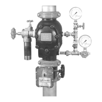
8. Open the system main drain valve to drain any water that has
accumulated and to release system air pressure.
NOTE: If the system has operated, open the remote system test valve
(inspector’s test connection) and any auxiliary drain valves.
9. Close the slow-fill ball valve on the AMTA.
WARNING
Makesurethevalveisdepressurized•
anddrainedcompletelybeforethe
coverplateboltsareremoved.
Thecoverplatecouldblowoffifthe
coverplateboltsareremovedwhilethe
valveispressurized,resultinginserious
personalinjuryand/orpropertydamage.
10. PUSHDOWNONTHEAUTODRAINSCREWTOREMOVE
PRESSUREINTHEDIAPHRAGMCHARGELINE.
11. After all pressure is released from the system, loosen the cover
plate bolts slowly. NOTE: DO NOT remove any cover plate bolts
until all cover plate bolts are loosened.
12. Remove all cover plate bolts, along with the cover plate and cover
plate gasket. NOTE: The 1 ½-inch/48.3-mm and 2-inch/60.3-mm
valve sizes contain washers under the heads of the cover plate
bolts. Keep these washers for re-installation.
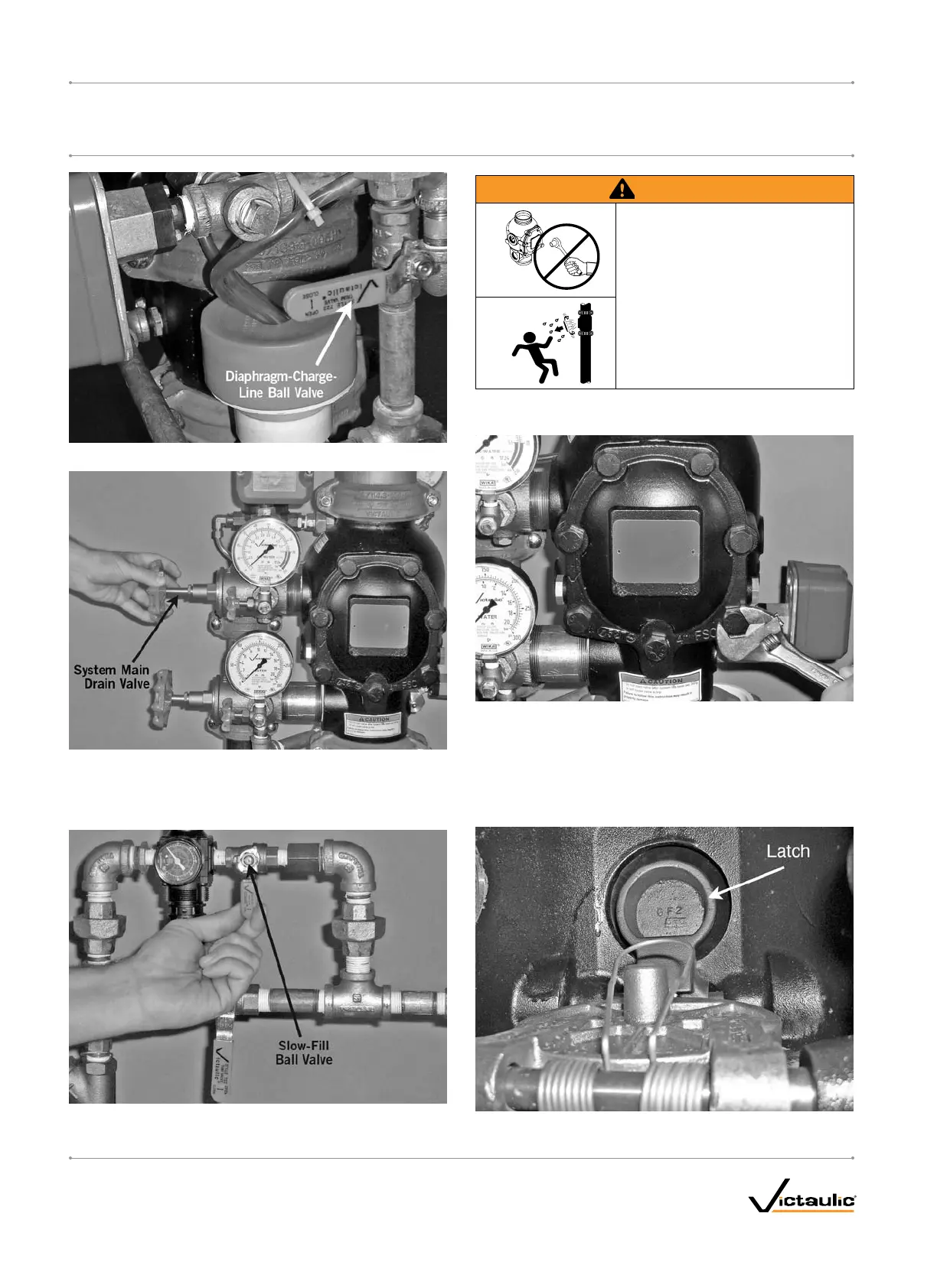
13. Push the latch back (toward the diaphragm).
I-768_30
FireLockNXT™DryValve
SERIES768
I-768INSTALLATION,MAINTENANCE,ANDTESTINGMANUAL
www.victaulic.com
VICTAULIC IS A REGISTERED TRADEMARK OF VICTAULIC COMPANY. © 2007 VICTAULIC COMPANY. ALL RIGHTS RESERVED. PRINTED IN THE USA.
REV_D

 Loading...