5. Place the new clapper assembly onto the valve-body seat ring.
Make sure the holes in the clapper arms align with the holes in the
valve body.
6. Insert the clapper shaft halfway into the valve body.
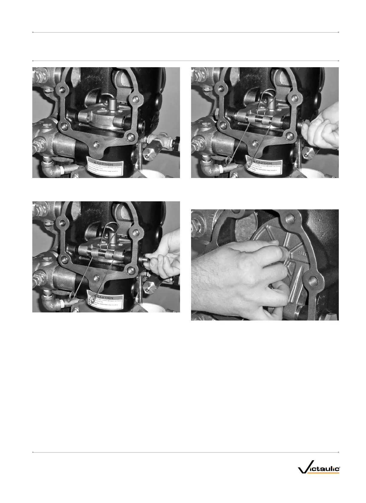
7. Install the clapper spring onto the clapper shaft. Make sure the
loop of the clapper spring is facing toward the clapper, as shown
above.
8. Finish inserting the clapper shaft through the clapper arm and
valve body.
9. Apply thread sealant to the clapper shaft bushings. Install the
clapper shaft bushings into the valve body until hand-tight.
10. Tighten the clapper shaft bushings until metal-to-metal contact
occurs with the valve body.
11. Check the clapper for freedom of movement.
12. Replace the cover plate by following the “Installing the Cover Plate
Gasket and Cover Plate” section.
13. Place the system back in service by following the “Placing the
System in Service” section.
I-768_35
FireLockNXT™DryValve
SERIES768
I-768INSTALLATION,MAINTENANCE,ANDTESTINGMANUAL
www.victaulic.com
VICTAULIC IS A REGISTERED TRADEMARK OF VICTAULIC COMPANY. © 2007 VICTAULIC COMPANY. ALL RIGHTS RESERVED. PRINTED IN THE USA.
REV_D

 Loading...