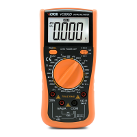
See
See
See
See
Figure3-9.RTD
Figure3-9.RTD
Figure3-9.RTD
Figure3-9.RTD
Measurement
Measurement
Measurement
Measurement
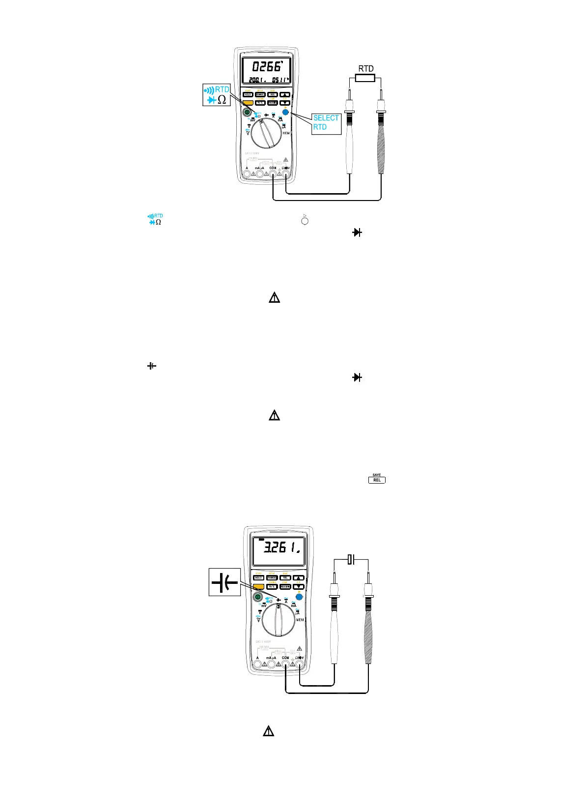
1. Set the rotary switch to position, and press blue button ( ) three times to select diodes testing.
2. Insert the black lead into “ COM
COM
COM
COM
” terminal, and the red lead to into the “ Ω
Ω
Ω
Ω
V
V
V
V
” terminal.
3. Connect the leads to the tested RTD .
4. Read the measuring results from the screen.
Measuring
Measuring
Measuring
Measuring
Capacitance
Capacitance
Capacitance
Capacitance
(
(
(
(
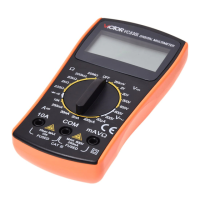
See
See
See
See
Figure3-10)
Figure3-10)
Figure3-10)
Figure3-10)
Warning
Warning
Warning
Warning
To
To
To
To
avoid
avoid
avoid
avoid
possible
possible
possible
possible
damage
damage
damage
damage
to
to
to
to
the
the
the
the
meter
meter
meter
meter
or
or
or
or
to
to
to
to
the
the
the
the
equipment
equipment
equipment
equipment
under
under
under
under
test,
test,
test,
test,
disconnect
disconnect
disconnect
disconnect
circuit
circuit
circuit
circuit
power
power
power
power
and
and
and
and
discharge
discharge
discharge
discharge
all
all
all
all
high-voltage
high-voltage
high-voltage
high-voltage
capacitors
capacitors
capacitors
capacitors
before
before
before
before
measuring
measuring
measuring
measuring
capacitance.
capacitance.
capacitance.
capacitance.
Use
Use
Use
Use
the
the
the
the
dc
dc
dc
dc
voltage
voltage
voltage
voltage
function
function
function
function
to
to
to
to
confirm
confirm
confirm
confirm
that
that
that
that
the
the
the
the
capacitor
capacitor
capacitor
capacitor
is
is
is
is
discharged.
discharged.
discharged.
discharged.
The meter ’ s capacitance ranges are 50.00nF 、 500.0nF 、 5.000 µ F 、 50.00 µ F 、 100.0 µ
F.
To test capacitance, proceed as follows:
1. Set the rotary switch to position to select capacitance measurement.
2. Insert the black lead into “ COM
COM
COM
COM
” terminal, and the red lead to into the “ Ω
Ω
Ω
Ω
V
V
V
V
” terminal.
3. Connect the leads to the tested capacitance.
4. Read the measuring results from the screen.
Caution
Caution
Caution
Caution
OL
OL
OL
OL
appears
appears
appears
appears
on
on
on
on
the
the
the
the
display
display
display
display
if
if
if
if
the
the
the
the
tested
tested
tested
tested
capacitance
capacitance
capacitance
capacitance
is
is
is
is
open
open
open
open
or
or
or
or
the
the
the
the
value
value
value
value
surpasses
surpasses
surpasses
surpasses
the
the
the
the
maxim
maxim
maxim
maxim
range.
range.
range.
range.
If
If
If
If
the
the
the
the
test
test
test
test
ed
ed
ed
ed
capacitance
capacitance
capacitance
capacitance
is
is
is
is
polar
polar
polar
polar
capacitance,
capacitance,
capacitance,
capacitance,
then
then
then
then
connect
connect
connect
connect
the
the
the
the
red
red
red
red
lead
lead
lead
lead
with
with
with
with
the
the
the
the
positive
positive
positive
positive
point
point
point
point
and
and
and
and
the
the
the
the
black
black
black
black
lead
lead
lead
lead
with
with
with
with
the
the
the
the
negative
negative
negative
negative
point.
point.
point.
point.
High
High
High
High
capacitance
capacitance
capacitance
capacitance
test
test
test
test
needs
needs
needs
needs
more
more
more
more
time,
time,
time,
time,
and
and
and
and
30s
30s
30s
30s
is
is
is
is
necessary
necessary
necessary
necessary
in
in
in
in
100
100
100
100
µ F
F
F
F
position.
position.
position.
position.
To
To
To
To
improve
improve
improve
improve
the
the
the
the
measurement
measurement
measurement
measurement
accuracy
accuracy
accuracy
accuracy
of
of
of
of
small
small
small
small
value
value
value
value
capacitors,
capacitors,
capacitors,
capacitors,
press
press
press
press
with
with
with
with
the
the
the
the
test
test
test
test
leads
leads
leads
leads
open
open
open
open
to
to
to
to
subtract
subtract
subtract
subtract
the
the
the
the
residual
residual
residual
residual
capacitance
capacitance
capacitance
capacitance
of
of
of
of
the
the
the
the
meter
meter
meter
meter
and
and
and
and
leads.
leads.
leads.
leads.
The
The
The
The
remaining
remaining
remaining
remaining
voltage
voltage
voltage
voltage
of
of
of
of
capacitance
capacitance
capacitance
capacitance
,
,
,
,
insulated
insulated
insulated
insulated
impedance
impedance
impedance
impedance
and
and
and
and
dielectric
dielectric
dielectric
dielectric
absorption
absorption
absorption
absorption
could
could
could
could
cause
cause
cause
cause
measuring
measuring
measuring
measuring
errors.
errors.
errors.
errors.
Only
Only
Only
Only
Auto
Auto
Auto
Auto
r
r
r
r
anging
anging
anging
anging
mode
mode
mode
mode
is
is
is
is
available
available
available
available
in
in
in
in
capacitance
capacitance
capacitance
capacitance
measurement.
measurement.
measurement.
measurement.
See
See
See
See
Figure3-10.
Figure3-10.
Figure3-10.
Figure3-10.
Capacitance
Capacitance
Capacitance
Capacitance
Measurement
Measurement
Measurement
Measurement
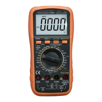
Measuring
Measuring
Measuring
Measuring
Current
Current
Current
Current
(
(
(
(
See
See
See
See
Figure3-11,
Figure3-11,
Figure3-11,
Figure3-11,
Figure3-12)
Figure3-12)
Figure3-12)
Figure3-12)
Warning
Warning
Warning
Warning
Never
Never
Never
Never
attempt
attempt
attempt
attempt
an
an
an
an
in-circuit
in-circuit
in-circuit
in-circuit
current
current
current
current
measurement
measurement
measurement
measurement
where
where
where
where
the
the
the
the
open-circuit
open-circuit
open-circuit
open-circuit
potential
potential
potential
potential
to
to
to
to
earth
earth
earth
earth
is
is
is
is
greater
greater
greater
greater
than
than
than
than
1000
1000
1000
1000
V.
V.
V.
V.
You
You
You
You
may
may
may
may
damage
damage
damage
damage
the
the
the
the
meter
meter
meter
meter
or
or
or
or
be
be
be
be
injured
injured
injured
injured
if
if
if
if
the
the
the
the
fuse
fuse
fuse
fuse
blows
blows
blows
blows
during
during
during
during
such
such
such
such
a
a
a
a