Operator’s Manual Backhoe Series BH - Page 33 of 91 - Version 2.0
Method:
1. Because of the assembling process, the tractor is already in place, and the PTO hydraulic
pump assembly is already connected. If this is not the case, do it anyway.
2. Ensure the boom pivot center point is 12” or 14” off the ground. Correct if necessary.
3. Carefully move the backside of the tractor close to the backhoe. Align the holes in the tractor
lower link arms to the lower link brackets. Insert the L-pins.
4. Start the PTO at low idle speed.
5. Carefully use the control handles for the boom or the stabilizers to align the hole in the
adjustable upper brace with the tractor upper link weldment. Insert the connection pin.
6. Check that the Backhoe swing pivot centerline is perpendicular to the ground. If not, use the
second lower link holes or adjust the upper brace.
7. Secure all connection pins with R-shaped cotter pins, or snap pins.
8. Lift the boom, retract the dipper stick, lift the bucket and move it close to the boom.
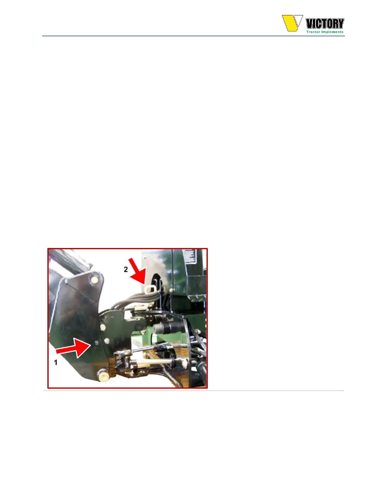
9. Engage the boom lock pin and the swing lock pin if you want to start transporting the
backhoe; otherwise, stop the PTO power.
Hole for Boom lock & Swing pivot lock pin
 Loading...