Switch
position
Suggested
battery type
Absorption
voltage* (V)
Float
voltage*
(V)
Equalize**
voltage* (V)
Equalize**
nominal
current
percentage
Temperature
compensation
factor* (mV/°C)
6
PzS tubular
plate traction
batteries or
OPzS batteries
15.3
30.6
61.2
13.8
27.6
55.2
17.1
34.2
68.4
25%
-16
-32
-64
7
Lithium Iron
Phosphate
(LiFePo4)
batteries
14.2
28.4
56.8
13.5
27.0
54
n/a n/a
0
0
0
* The top value is for 12V systems, the middle for 24V systems and the bottom for 48V systems.
** Equalize is by default disabled. To enable see chapter Battery settings [17]
A binary LED code helps determining the position of the rotary switch. After changing the position of the rotary switch, the LEDs
will blink during 4 seconds as indicated in below table. Thereafter, normal indication resumes, as described in the LEDs section.
Switch position Bulk LED Absorption LED Float LED Blinking frequency
0 1 1 1 Fast
1 0 0 1 Slow
2 0 1 0 Slow
3 0 1 1 Slow
4 1 0 0 Slow
5 1 0 1 Slow
6 1 1 0 Slow
7 1 1 1 Slow
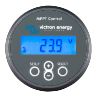
5.1.3. Settings via MPPT Control display
The optional MPPT Control display can be used to configure solar charger settings, with the exception of advanced settings such
as RX and TX port settings. For information on how to do this see the MPPT Control manual.
The MPPT Control
5.2. All settings explained
This chapter lists all solar charger settings that are user-configurable and also explains how to update firmware of the solar
charger.
Do not change settings unless you know what they are and what the effect of changing these settings will
be. Incorrect settings may cause system problems including damage to batteries. When in doubt, seek advice
from an experienced Victron Energy installer, dealer or distributor.
MPPT solar charger manual
Page 16 Configuration and settings
 Loading...