32
Privacy duration time (factory preset unlimited duration)
Press and hold (for approx 10 seconds) the “
” button until the rele-
vant LED illuminates and the unit beeps.
Each time the “
” button is pressed, it will increase (starting from 0)
the privacy duration by 15 minutes, press until the required duration
has been reached, when reached, wait 5 seconds the exit beep and
the LED turning OFF.
The new time will be stored.
To set the privacy with no time out (privacy enabled or disabled by press-
ing the “
” button), don't press any buttons once in privacy programming
mode and wait 5 seconds for the beep and LED to go off.
Per programmare la durata della “privacy” (di fabbrica infinito)
Premere e tenere premuto (10 secondi circa) il pulsante “
” fino a
quando il relativo LED si accende e l’unità emette un bip.
Ogni pressione del tasto “
” incrementa (partendo da 0) la durata del
servizio privacy di 1/4 d’ora: premere fino a raggiungere la durata
desiderata (max 80 volte = 20 ore). Impostato il valore , attendere
circa 5 secondi il bip di uscita e lo spegnimento del LED
Il nuovo valore è memorizzato.
Per impostare la durata illimitata (servizio attivato e disattivato tramite il
pulsante“
”), entrare in programmazione eseguendo il primo passo ed
attendere l’uscita senza premere nulla.
Door Opening Time Programming (factory preset 1 second)
Press and hold the “
” button (for approx 10 seconds) until the unit
emits a beep.
Press the “
” button for the number of seconds required minus 1
(i.e. for 6 seconds press 5 times up to a maximum of 255 seconds).
Once the required door open time has been reached, wait 5 seconds
for the exit beep.
The new value is now stored.
Programmazione del tempo d’apertura porta (di fabbrica = 1s)
Premere e tenere premuto per circa 10 secondi il pulsante “
” fino
a che il videocitofono non emette un bip;
Premere il pulsante “
” tante volte quant’è il numero di secondi che
si vuole impostare meno 1 (Es.6 secondi = 5 volte max 255 secondi);
Raggiunto il valore desiderato, attendere 5 secondi fino all’emissione
di un bip;
Il nuovo tempo d’apertura porta è memorizzato.
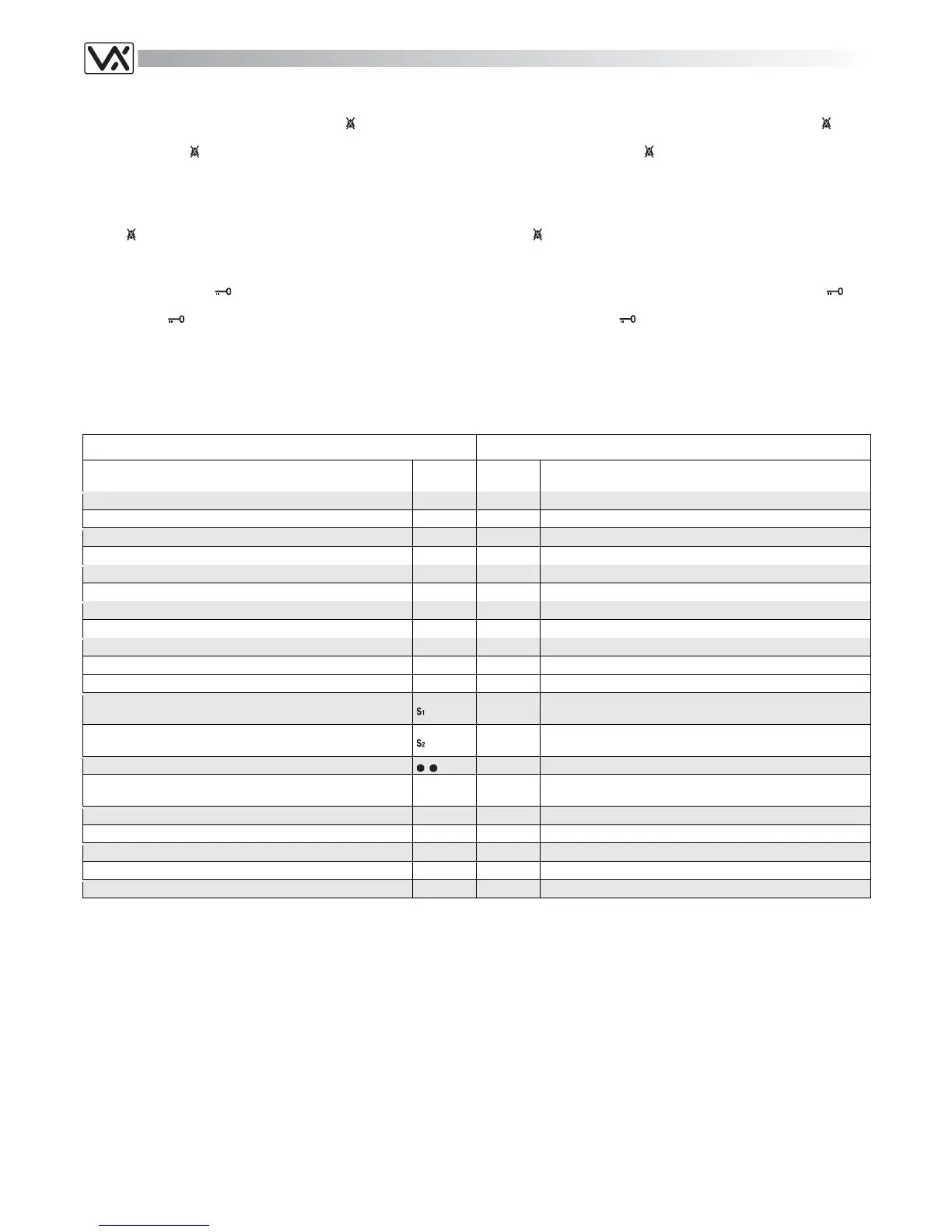
Terminals and relevant signals
The table that follow shows the signals available on the terminals (from 1
to 20) of the PCB supplied with the videomonitor.
Morsetti e relativi segnali
La tabella che segue mostra i segnali presenti sui morsetti della scheda di
connessione (1..20), inclusa nel videocitofono.
ART.SL5418 SIGNALS ON TERMINALS ART.SL5418 SEGNALI MORSETTIERA
Signal Description
Segnale
Signal
Morsetto
Terminal
Descrizione Segnale
+20V power input
+20V 1 Ingresso +20V
+20V power input
+20V 2 Ingresso +20V
Ground
GND 3 Massa
Ground
GND 4 Massa
Coax = V input, Balanced video = V2 input
V2/V 5 Coax = Ingresso V, Video Bilanciato = ingresso V2
Balanced video signal V1 input
V1 6 Ingresso segnale video bilanciato V1
Speech line output from handset’s microphone
3 7 Uscita linea fonica dal microfono della cornetta
Camera recall signal output
T 8 Uscita segnale di auto-accensione
Local bell input (active low)
LB 9 Ingresso per chiamata di piano (attivo basso)
Door open signal output
5 10 Uscita comando apri-porta
12Vdc power supply input auxiliary LED
LDA 11 Ingresso di alimentazione 12Vdc per LED ausiliario
Service button: link the terminal to ground until the button re-
main pressed (max 24Vdc 200mA).
12
Pulsante di servizio: chiude verso massa fino a quando resta
premuto (max 24Vdc 200mA).
Service button: link the terminal to ground until the button re-
main pressed (max 24Vdc 200mA).
13
Pulsante di servizio: chiude verso massa fino a quando resta
premuto (max 24Vdc 200mA).
Second camera recall button for two entrances systems.
14 Secondo pulsante di auto-accensione per sistemi a 2 ingressi.
+12V output to supply the video distributor Art.894/894N (co-
axial video signal mode)
+VD 15
+12Vdc per alimentare il distributore video Art.894/894N in
modo video coassiale
Speech line input toward the handset’s loudspeaker
4 16 Ingresso fonia verso l’altoparlante della cornetta
+12Vdc stabilized output
12VO 17 Uscita stabilizzata +12Vdc
+12Vdc input
12VI 18 Ingresso di alimentazione +12Vdc
+12Vdc door open / auxiliary LED
LD 19 Ingresso di alimentazione +12Vdc LED porta aperta / ausiliare
Call tone input
C 20 Ingresso nota di chiamata
Table 11
Tabella 11
Technical Specification Specifiche Tecniche
Voltages
Videophone 20Vdc (+2-5V)
12Vdc (+1-4V)
Power Consumption Stand-by Operating
20Vdc 0mA 250mA
12Vdc 20mA 50mA
Tensioni di alimentazione
Videocitofono 20Vdc (+2-5V)
12Vdc (+1-4V)
Assorbimento A riposo In funzione
20Vdc 0mA 250mA
12Vdc 20mA 50mA