34
ART.SL5418-5418 FLUSH MOUNT USING ART.5981N ART.SL5418-5418 MONTAGGIO DA INCASSO CON ART.5981N
d
d
g
a
d
g
e
f
b
d
c
l
l
l
l
h
i
Fig.1 Fig.2 Fig.3
i
h
p
Fig.4 Fig.5 Fig.6
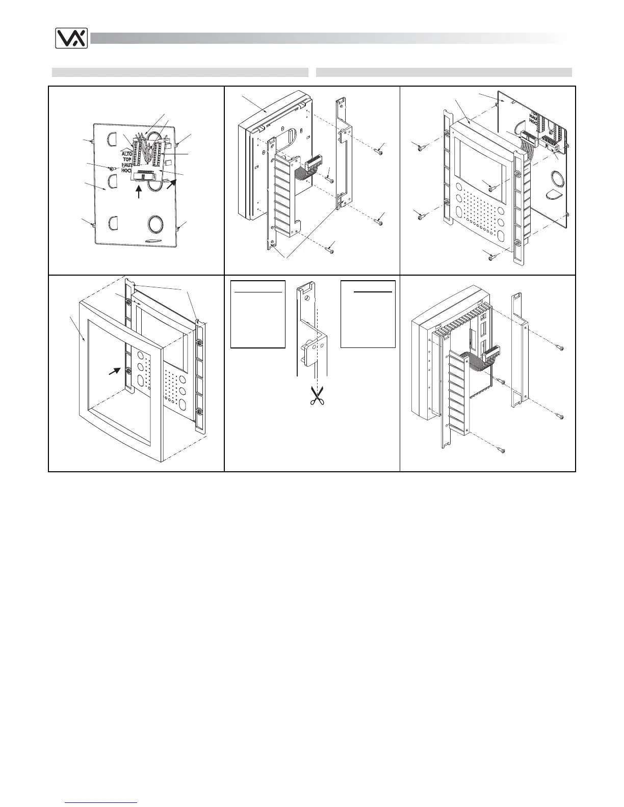
Protect the videophone fixing holes “d” (Fig.1) from dust then embed
the flush back box “a” (Fig.1) into the wall (about 135cm between the
bottom of the box and the floor level as shown on the Figure 1 on
page 33). Observe the direction of the box (see instruction on the
bottom of the box) and take care that the box profile is in line with the
finished wall profile;
Hook the pcb connection board “b” to the flush mounting box “a” as
shown in figure 1 (see pointers) feeding the cables “e” through the
opening “f” then fix the connection board using the screw “c”;
With the connection board “b” fitted, connect the wires to terminal “g”
(Fig.1) as shown in the diagram provided;
Arrange the videophone “h” fixing to it the two brackets “i” using the 4
screws “l” as shown in figure 2. If the videomonitor is not a slim
line model, first arrange the brackets by cutting their upper and low-
er sides as shown in figure 5 then, as described above, fix the brack-
ets to the videomonitor as shown in figure 6;
As shown on figure 3, move the videophone “h” close to the back
box, connect the plug “m” on the ribbon cable from the videophone to
the plug “n” on the pcb connection board then fix the videophone “h”
to the back box “a” using the four screws “o”;
• As shown on figure 4, align the frame “p” with the brackets “i” then
push it toward the wall until the frame is hooked.
Proteggere opportunamente i fori di fissaggio “d” (Fig.1) quindi mura-
re la scatola da incasso “a” lasciando circa 135cm tra la parte inferio-
re della scatola ed il pavimento (Fig.1 pag.33). Fare attenzione al
verso della scatola (vedi le indicazioni sul fondo della stessa) e a che
venga murata a filo muro finito;
Agganciare la scheda di connessione “b” alla scatola da incasso “a”
come mostrato in figura 1 (vedi verso delle frecce) facendo passare i
fili “e” attraverso l’apertura “f” quindi fissare la scheda alla scatola
tramite la vite “c”;
Una volta fissata la scheda di connessione “b”, collegare i fili ai mor-
setti “g” (fig.1) in accordo con quanto indicato nello schema di con-
nessione fornito a corredo;
Preparare il videocitofono “h” montando le due staffe “i” utilizzando le
4 viti “l” come mostrato in figura 2. Se il videocitofono da incasso
non è di tipo slim, preparare le staffe tagliando la parte (sia superio-
re che inferiore) mostrata in figura 5, quindi analogamente a come
sopra descritto fissare le staffe al videocitofono come mostrato in fi-
gura 6;
Come mostrato in figura 3, avvicinare il videocitofono “h” alla scatola
da incasso, collegare il connettore “m” del cavo flat che fuoriesce dal
videocitofono al connettore “n” della scheda di connessione quindi
fissare il videocitofono “h” alla scatola da incasso “a” utilizzando le 1
viti “o”;
Come mostrato in figura 4, allineare la cornice “p” con le staffe “i” e
premere la stessa verso il muro fino all’aggancio.
RICORDA!
Il taglio delle
staffe non è
richiesto per i
videocitofoni
della linea
SLIM
REMEMBER!
For slim line
videomonitors
the cut of the
brackets is
not required