- 15 -
6200 Series
Art.6296 - Installation instructions
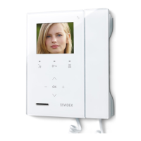
VIEW THE EVENT LOG
The videophone stores a list of events (external calls and internal calls) with the event date & time. On any external call, the video-
phone stores also a picture of the visitor. The events are described by 2 icons (a speaker unit for door panel events and an intercom
for indoor station events) and 3 dierent colours:
• green = external/internal incoming call answered.
• blue = Outgoing calls. Camera recall if the icon is a speaker unit and intercommunicating if the icon is a intercom.
• red = external/internal incoming call missed.
• Tap on the event log icon (Fig. 61).
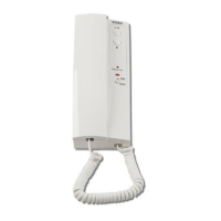
• Tap on the event that you want to inspect (Fig. 62)
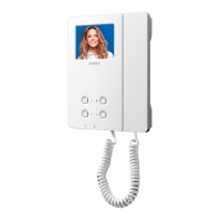
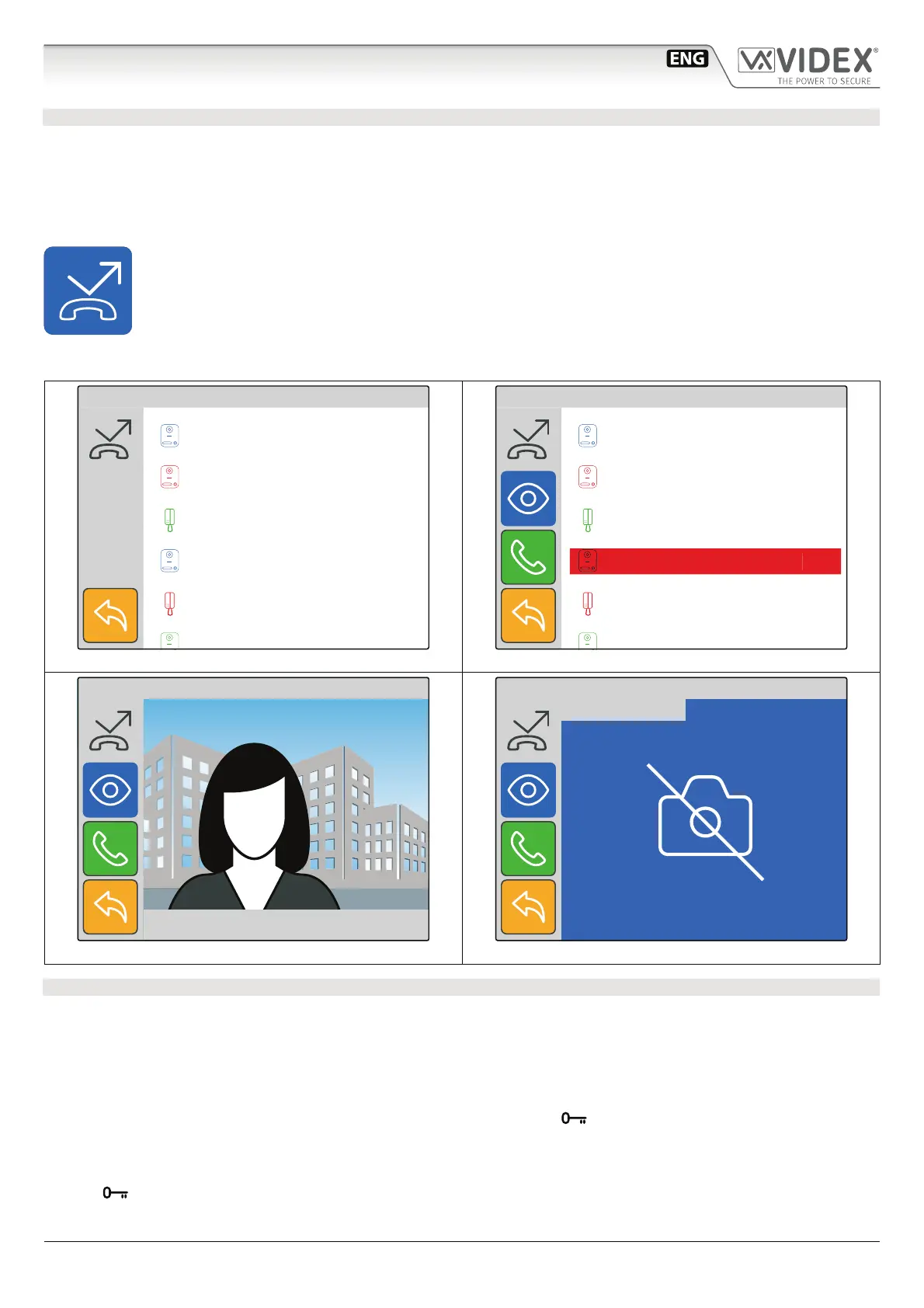
• You can tap and keep pressed the eye icon to see a picture showing the event source, date & time if it is an exter-
nal communication (Fig. 63) or no picture (Fig. 64) in all other cases.
• Once you have selected the event you can tap on the call button: the call will proceed as a camera recall
(“Camera recall” on page 10) if it is a door panel event otherwise it will proceed as an intercommunicating
call (“Intercommunicating call” on page 12) if it is an indoor station event.
10:00 21/06/2017
12:30 22/06/2017
15:00 22/06/2017
15:18 22/06/2017
16:00 22/06/2017
EVENT LOG
Fig. 62 External missed call
15:30
EVENT LOG
Main Entrance
15:18 22/06/2017
Fig. 63 External lost call picture stored
15:30
EVENT LOG
18:34 13/04/17
Fig. 64 Internal missed call
INPUTS / OUTPUTS OPERATION
The operation of the input/output terminals is not programmable and operate how follows:
• When IN1 is active (active low input) or when the videophone is in the ringing status, relay 1 is activated: terminals “OUT1” will
link internally (i.e. it can be used to activate an external sounder when the visitor calls from outside the or if someone presses
the local bell connected to IN1 and GND). Please see example diagram on pag. 39.
• While the videophone is ringing or in conversation with a door panel, if IN2 is active/triggered (active low input), the video-
phone sends a command to enable relay one of that door panel. This operation will be useful in cases where only authorised
personnel are allowed to open the door/gate from the handset (i.e. with the
button disabled, and a volt free output of an
access control keypad/proximity system connected to IN2 and GND of the 6296 the user will have to activate the keypad or
proximity system in order to open the door/gate). Please see example diagram on pag. 39.
Please note; If this operation is required, ensure the relevant controlled outputs are not present in the service list of the videophone
and the
button is also disabled.
Art.6296
IP Videophone for VIDEX IP System
 Loading...