66250675-EN - V1.0 - 05/09/17
46
4000 Series Vandal Resistant GSM - Technical Manual
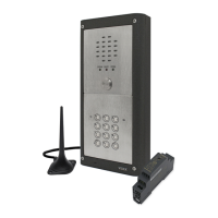
4000 Series Vandal Resistant GSM Audio Intercom with Proximity Facility
Programming the GSM Intercom
ENABLE PROXIMITY READER EPR
IMPORTANT NOTE: As the Art.VR4KGSM module does not have a built-in proximity reader a Wiegand proximity reader (Art.
VR4KPPM) must rst be connected to the GSM intercom (refer to notes on page 21 and 22 for connection) and then enabled.
The Wiegand proximity reader can be enabled or disabled. By default this function is disabled. The following programming texts are
used to enable or disable the proximity reader.
1111EPRnn Set proximity reader nn: 01 or 00 (01 = enabled, 00 = disabled).
1111EPRnn? Set proximity reader nn: 01 or 00 (01 = enabled, 00 = disabled) and send a conrmation
text back to the sender.
1111EPR? Query mode. A text message will be sent back to the sender conrming if the proximity
reader is enabled or disabled.
PROXIMITY NUMBER OF BYTES TO CHECK PBY, 02, 03 & 04
This function will only be applicable if the Wiegand proximity reader has been connected and enabled (see EPR function above).
After the proximity reader is enabled the number of bytes that the reader checks is dependant on which type of proximity fob/card
is used (also refer to the GSM PC software manual GSMSK-66251720-EN-V1-3 (or later).
Understanding the Fob Format and Card Number
It is important to understand the relationship between the fob format and the card number when setting up the proximity reader
to check for the correct number of bytes.
• Fobs/Cards with 5 digit number (user code): If a proximity fob/card has no site code but a 5 digit user code
(e.g. 955/T or 955/C) the PBY format should be set to check for 2 bytes (02).
• Fobs/Cards with 3 digit site code and 5 digit user code: If using a fob/card with a 3 digit site code and 5 digit
user code (e.g. PBX1E or PBX2) the PBY format can be set to check for 2 bytes (02) or 3 bytes (03).
• Fobs/Cards programmed using the PROXE desktop reader: If using the PROXE desktop reader the PBY format
can be set to check for 2 bytes (02), 3 bytes (03) or 4 bytes (04).
The default setting for this function is set to check for 2 bytes, ‘02’. The following texts can be used to change this setting.
1111PBYnn Set proximity reader to check for number of bytes nn: 02, 03 or 04 (02 = check for 2 bytes,
03 = check for 3 bytes, 04 = check for 4 bytes).
1111PBYnn? as above and send a conrmation text back to the sender.
1111PBY? Query the number of bytes that the GSM PRO has been set to check for.
PBY setting Description
2 bytes Will read all fobs/cards types programmed.
3 bytes Will not read fobs/cards programmed with only 2 bytes (5 digit) information.
4 bytes Will not read fobs/cards programmed with only 2 bytes (5 digit) or 3 bytes (8 digit) information.
IMPORTANT NOTE: It is recommended that only one fob/card type is used to allow for easier set up and programming of the
proximity reader. HID and Mifare cards cannot be used.
STORE/QUERY A PROXIMITY FOB/CARD FOB, 000 999
Once the built-in proximity reader has been enabled and the number of bytes to check for has been set (refer to the EPR and PBY
setup described above) the proximity fobs/cards can be programmed into the GSM intercom.
The GSM intercom can store up to 1000 fobs/card (000 - 999). The Art.VR4KPPM proximity reader can be programmed with any one
of the following fobs:
• 955/T or 955/C = Videx fobs or cards. These fobs and cards have no site code and have a 5 digit user code, so
the PBY function must be set to 02 (the default setting, checking for 2 bytes).
• PBX1E or PBX2 = Portal Plus fobs or cards. These fobs and cards have a 3 digit site code and 5 digit user code,
so the PBY function can be set to 02 or 03.
The following texts can be used to program fobs or cards.
1111FOBnnn”site”,”user” Store fob/card in location nnn, where nnn = the memory location from 000 - 999 of where
the fob/card is actually stored (see examples below for each type of fob/card). The “site”
and “user” code is the number taken directly from the fob/card.

 Loading...