Do you have a question about the Viessmann Vitogate 300 and is the answer not in the manual?
Explains danger, material loss, and general notes symbols used in the manual.
Specifies intended users and regulatory requirements for installation and environmental protection.
Outlines essential safety measures for working on the system, including electrical and gas isolation.
Provides specific clearance dimensions for different boiler heating outputs in a detailed table.
Details all labeled connections on the boiler for heating water, including return, drain, and safety connections.
Guides the installation of the flue outlet and siphon, including connection to the flue pipe and filling with water.
Covers the attachment of the boiler door, emphasizing diagonal tightening and gasket check for leaks.
Details the preparation steps for installing the control unit, including locating the boiler coding card.
Covers connecting cables and leads for the control unit and securing the mounting bracket fascia.
Details adjusting the burner with the rotary damper open, setting CO2 content for optimal efficiency.
Outlines requirements for commissioning, including minimum operating pressure and the use of pressure switches for safe operation.
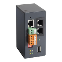
| Power supply | 24 V DC |
|---|---|
| Communication | Ethernet |
| Communication protocols | BACnet |
| Functions | Data logging, remote monitoring |
| Weight | 0.2 kg |
| Mounting | Wall mounting / DIN rail mounting |