4 Vitolig 200
M
qQ
M
4
8
3
2
9
7
6
8
7
6
5
qT
qE
qR
qW
Vitolig 200 Buffer storage unit
Vitocell 050
Vitocell−B
or
1
Vitocell
qW
qQ
qP qP
37
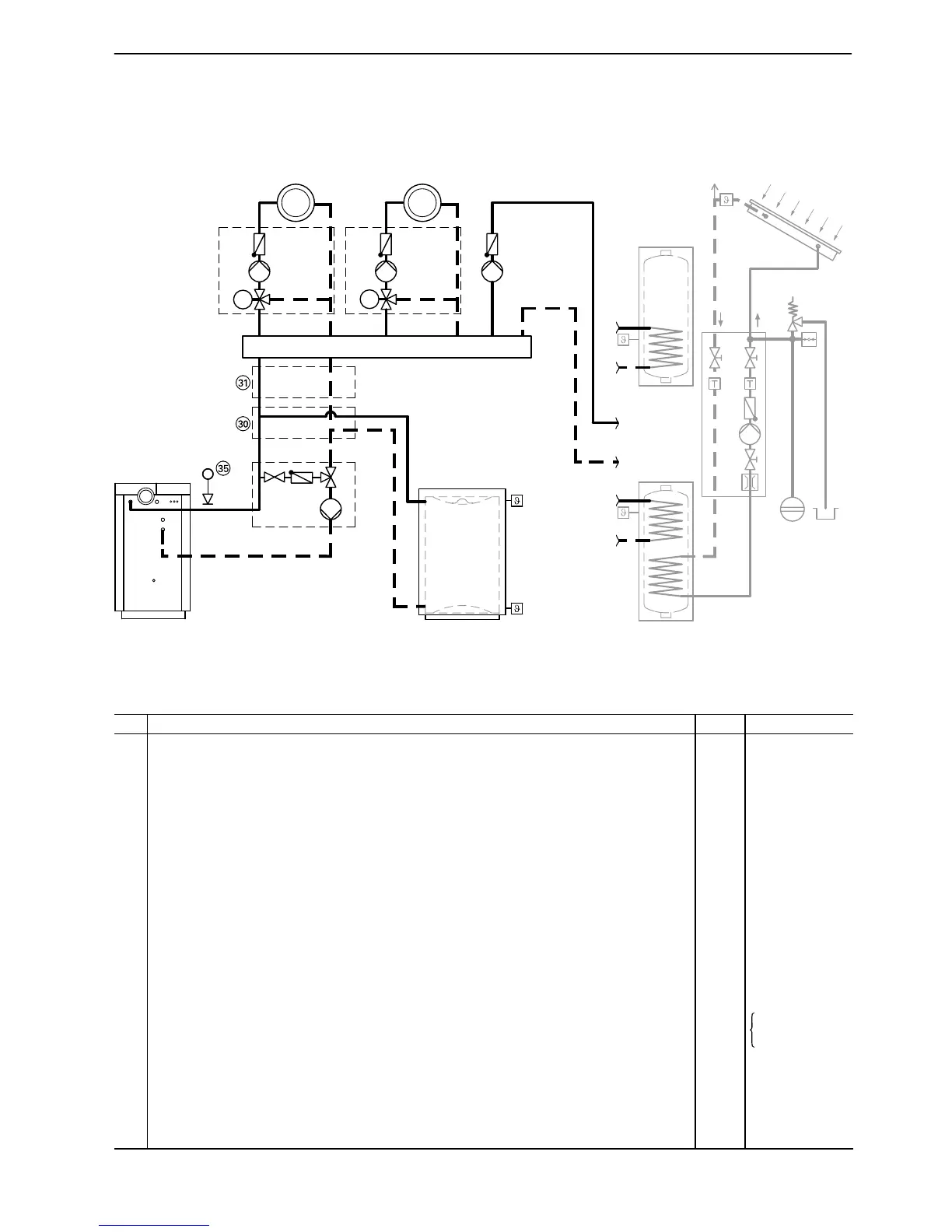
Installation diagram for application example 1
Required equipment
Item
Description No. Part no.
1 Buffer loading controller PLR2 (part of standard delivery of Vitolig 200) 1
2 Return temperature raising facility 1 7159062
3 Boiler circuit pump (part of standard delivery of return temperature raising facility) 1
4 Mixing valve with check valve (part of standard delivery of return temperature raising facility) 1
5 Circulation pump for DHW cylinder with check valve 1 7339 467
6 Modular Divicon 1(2) see price list
7 Heating circuit pump (part of standard delivery of modular Divicon) 1(2)
8 Heating mixer 3 (part of standard delivery of modular Divicon) 1(2)
9 Flow and return distributor for modular Divicon 1 see price list
qP Heating circuit controller HKR for regulating a heating circuit with mixer and one DHW
cylinder with remote control
1(2) 7159 789
Outside temperature sensor 1 7159 817
qQ Mixer motor 1(2) 7450657
qW DHW cylinder temperature sensor 1 7159 822
qE Temperature sensor at top of heating water buffer storage unit 1 part of standard
qR Temperature sensor at bottom of heating water buffer storage unit 1
delivery of
Vitolig200
qT Sensor well 2 7265060
eP Connection unit heating water buffer storage unit 1 7159 406
eQ Transition unit 1 7159 411
eT Low water limiter (low water indicator) 1 9529 050
eZ Thermostatic drain valve 1 7143 845
5822241 GB







 To Next Page