4 Vitolig 200
38
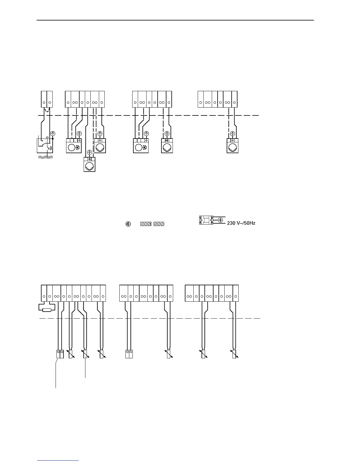
Wiring diagram for application example 1
Connection of circulation pumps, mixer motors and low water indicator
Connection for temperature sensors and remote control units
Connection of solar heating components see Technical Guide for Solar Heating Systems, application example 1.
5822241 GB
XW Buffer loading controllerHeating circuit 2Heating circuit 1
Boiler circuit pump 3
XN/N
XN/LI
Heating circuit
pump 7
Mixer
motor qQ
Heating circuit
pump 7
Low
water
indicator
eT
L
N
L
N
1
N
2
X44
X65
N
6
X98
3
7
X2
1
2
L
N
1
N
2
X44
X65
N
6
X98
3
7
X2
1
N
2
X44
X65
N
6
X98
3
7
L
N
X2
Circulation pump for
DHW heating
5
Mixer
motor qQ
Mains electrical connection
on
N
close(d)
M
on
N
close(d)
M
R2
5
6
120
Heating circuit 1
Outside
temperature
sensor
1
2
Y34
Y45
Gnd
6
Y58
3
7
Y2
Y79
Gnd
10
11
L+12
L−13
Gnd
Heating circuit 2
Flow
temperature
sensor
Remote
control
1
2
Y34
Y45
Gnd
6
Y58
3
7
Y2
Y79
Gnd
10
11
6
5
Gnd
Buffer loading controller
Buffer
temperature
sensor
bottom
qR
1
2
Y34
Y45
Gnd
6
Y58
3
7
Y2
Y79
Gnd
10
11
Gnd
Buffer
temperature
sensor
top qE
Flow
temperature
sensor
DHW
temperature
sensor
qW
Remote
control







 To Next Page