23
Warning!
Do not use unit without positive earth connec-
tion (PE, ) !
Interrupt current connection before opening!
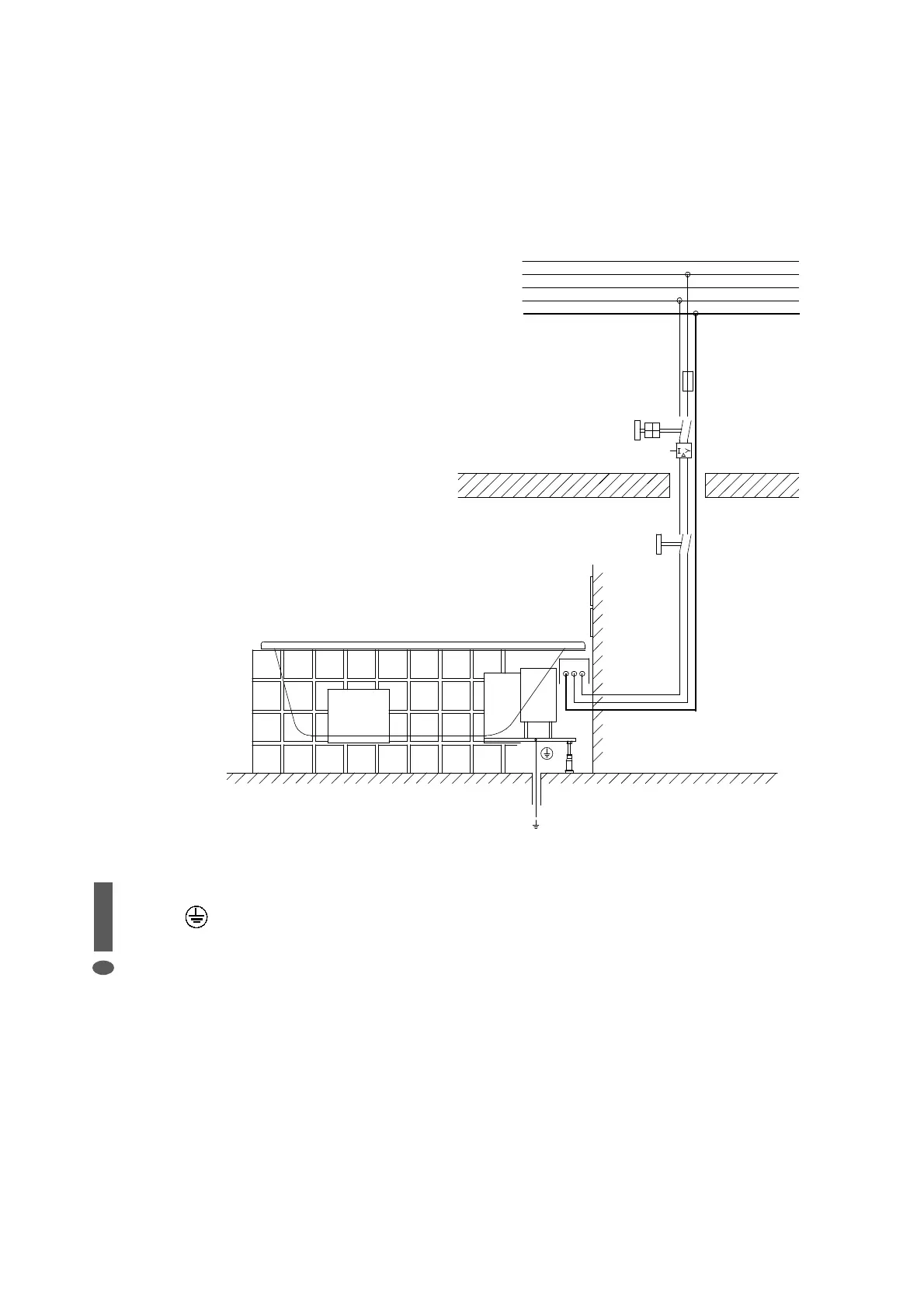
3.2 Electrical installation diagram
The site connection must be made using the
permanently installed wet room junction box
(IP 65, at least 30 cm above the fl oor in the
area below the tub).
An all-pole switch (isolation points at least 3
mm) and a 30 mA RCCB must be connected
upstream of the unit. The system is to be iso-
lated from the power supply using the all-pole
main isolation switch if it not to be used for
a lengthy period of time (holiday, etc.). When
you wish to use the tub again it must be disin-
fected as described in the operating instruc-
tions.
3.3 Earthing
The site equi-potential bond is to be connect-
ed to the earthing terminal on the tub frame.
A 4 mm² green and yellow cable is required for
this purpose.
L 1
L 2
L 3
N
10 A time-lag
RCD 30 mA
Main switch in bathroom
(Positioned outside area 2 in
accordance with VDE 0100 Teil 701)
Equipotential bonding 4 mm²
Subject to technical alterations! Warranty is only granted, if all mentioned instructions were followed.